Mass attenuation measurement method and device based on gamma-ray full-energy peak

A technique for mass attenuation, measurement method

Pending Publication Date: 2020-07-07
NAT INST OF METROLOGY CHINA
View PDF3 Cites 1 Cited by
  • Summary
  • Abstract
  • Description
  • Claims
  • Application Information

AI Technical Summary

Problems solved by technology

[0004] The existing technology cannot measure the mass attenuation coefficient when the sample composition is unknown and X-ray fluorescence analysis cannot be performed on the sample
At the same time, X-ray fluorescence spectrometry has certain limitations in the analysis of sample components. This method cannot analyze the content of ultralight elements (H, Li), and for organic compounds with high H element content (such as biological samples), it cannot analyze H element mass percentage

Method used


Image

  • Mass attenuation measurement method and device based on gamma-ray full-energy peak
  • Mass attenuation measurement method and device based on gamma-ray full-energy peak
  • Mass attenuation measurement method and device based on gamma-ray full-energy peak

Examples


Embodiment 1

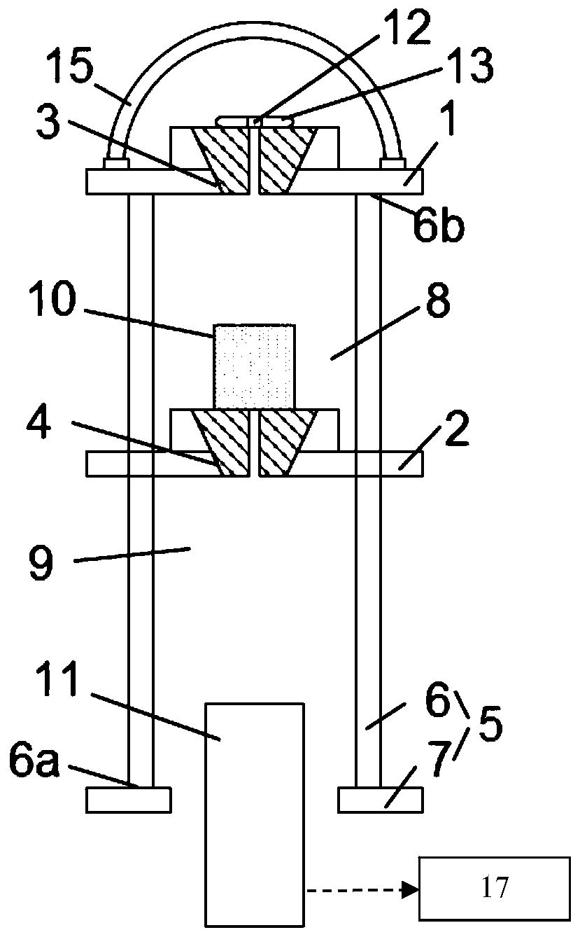
[0034] Such as figure 1 As shown, the present invention provides a mass attenuation measurement device based on the full energy peak of gamma rays, which at least includes a second lead collimator 1 , a first lead collimator 2 and a bracket 5 . Both the second plumb collimator 1 and the first plumb collimator 2 are arranged on the bracket 5 so that the extension direction of the second plumb collimator 1 and the extension direction of the first plumb collimator 2 can be parallel to each other. For example, the second lead collimator 1 can be in the shape of a hollow cylinder to define the first through hole 3 . The first lead collimator 2 can be in the shape of a hollow cylinder and thereby define a second through hole 4 . The central axis of the first through hole 3 and the central axis of the second through hole 4 can coincide with each other, so that the extension direction of the second plumb collimator 1 and the extension direction of the first plumb collimator 2 can be ...

Embodiment 2

[0044] This embodiment is a further improvement on Embodiment 1, and repeated content will not be repeated here.

[0045] Preferably, the mass attenuation measurement device further includes a data processor 17 that can be wired or wirelessly connected to the detector 11, so that the data collected by the detector 11 can be transmitted to the data processor 17 for processing. Data processor 17 completes data processing as follows:

[0046] S1: Obtain the gamma energy spectrum of the radioactive source 12 based on the data collected by the detector 11, and calculate the count rate corresponding to the peak position.

[0047] Preferably, the measurement time at the detector 11 is t live When , the count rate can be obtained from the ratio of the area of ​​the all-energy peak to the time. For example, the count rate can be calculated by the formula to represent, where n i (E) represents the count rate. N i (E) represents the net peak area of ​​the all-energy peak.

[0048...

Embodiment 3

[0055] This embodiment is a further improvement on the foregoing embodiments, and repeated content will not be repeated here.

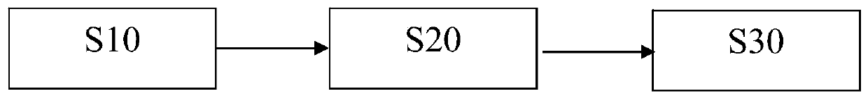
[0056] Such as image 3 As shown, the present invention also provides a kind of mass attenuation measurement method based on gamma ray full-energy peak, at least comprises the following steps:

[0057] S10: Configure the radiation source 12 and the detector 11, so that the radiation generated by the radiation source 12 can travel along a set direction and enter the detector 11, and prompt the detector 11 to generate first data.

[0058] Specifically, such as figure 1As shown, both the radiation source 12 and the detector 11 can be arranged on the bracket 5 to fix their relative positions. For example, the stand 5 includes at least two support rods 6 and a base 7 . The shape of the base 7 can be defined by a disc shape. All the support rods 6 can be arranged on the base 7, so that each support rod 6 can be parallel to each other. For example, the ...


PUM


Abstract

The invention relates to a mass attenuation measurement method based on a gamma-ray full-energy peak. The method at least comprises the steps of 1, configuring a radioactive source and a detector, arranging an empty sample box for placing a sample to be detected between the radioactive source and the detector, enabling radioactive rays generated by the radioactive source to enter the detector in atransmission mode in the set direction, promoting the detector to generate first data, arranging a sample to be detected between the radioactive source and the detector, enabling the radioactive raysgenerated by the radioactive source to enter the detector in a mode of penetrating through the sample to be detected when being transmitted along the set direction, and promoting the detector to generate second data; and acquiring a first counting rate n1 (E) based on the first data, acquiring a second counting rate n2 (E) based on the second data, and enabling the mass attenuation coefficient [mu]m (E) of the sample to be detected to the radioactive source to be expressed through a formula shown in the description, wherein h is the thickness of the sample to be detected.

Description

technical field [0001] The invention belongs to the technical field of mass attenuation measurement, and in particular relates to a mass attenuation measurement method and device based on the gamma ray full energy peak. Background technique [0002] When X (or γ) rays pass through matter, due to various interactions with medium particles (photoelectric effect, Compton effect, electron pair effect, coherent flash, photonuclear reaction, nuclear resonance effect, etc.), X (or γ) γ) rays have a certain probability of interacting with absorbing substances to be absorbed, or scattered and then the energy changes and deviates from the original incident direction. Photons that have not interacted pass through the absorbing layer with their energy unchanged. Therefore, when gamma rays pass through matter, their intensity gradually decays. In order to characterize the degree of attenuation of X (or γ) rays after passing through matter, the mass attenuation coefficient (also known a...

Claims


Application Information

Patent Timeline
Patent Type & Authority Applications(China)
IPC IPC(8): G01N23/10
CPCG01N23/10
Inventor 刘皓然李则书梁珺成邱向平
Owner NAT INST OF METROLOGY CHINA
Why Eureka
Try Eureka