Phase correction method and meteor position acquisition method

A technology of phase correction and acquisition method, applied in the field of phase correction and radar system phase correction

Inactive Publication Date: 2020-07-07
INST OF GEOLOGY & GEOPHYSICS CHINESE ACAD OF SCI
View PDF9 Cites 7 Cited by
  • Summary
  • Abstract
  • Description
  • Claims
  • Application Information

AI Technical Summary

Problems solved by technology

However, this method needs to know the flight path of the aircraft, and at the same time requires the fl

Method used


Image

  • Phase correction method and meteor position acquisition method
  • Phase correction method and meteor position acquisition method
  • Phase correction method and meteor position acquisition method

Examples


example 1

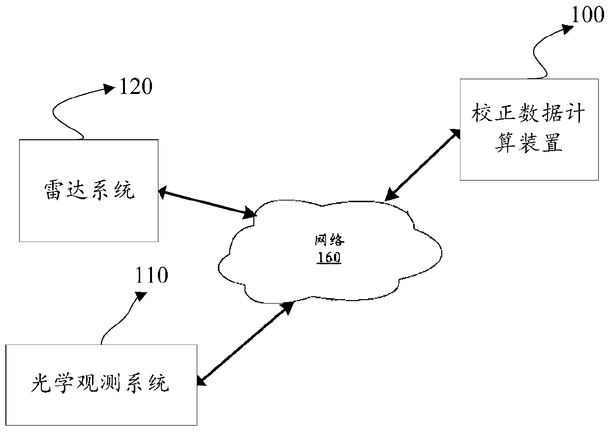
[0050] In Example 1, the optical observation system can be used to calculate the spatial position information of the meteor and determine the correction data of the radar system 120 , so the solution of Example 1 does not need the correction data calculation device 100 .

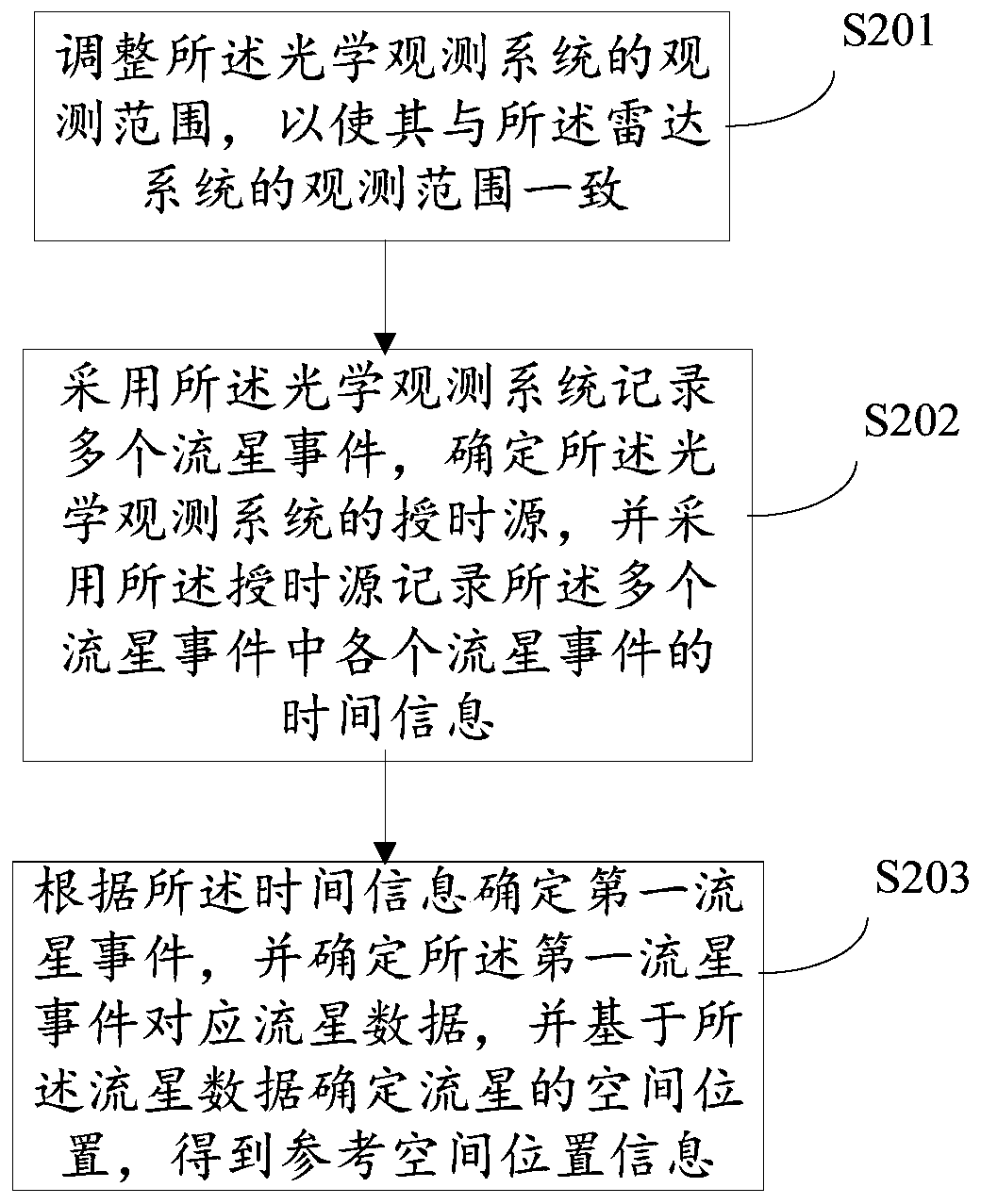
[0051] Such as figure 2 As shown, the figure is the flow of the method for the optical observation system 110 to acquire meteor position information.

[0052] figure 2 The shown method for obtaining meteor position information includes: S201, adjusting the observation range of the optical observation system 110 so that it is consistent with the observation range of the radar system; S202, using the optical observation system 110 to record multiple meteors Event, determine the timing source of the optical observation system 110, and use the timing source to record the time information of each meteor event in the plurality of meteor events; S203, determine the first meteor event according to the time inform...

example 2

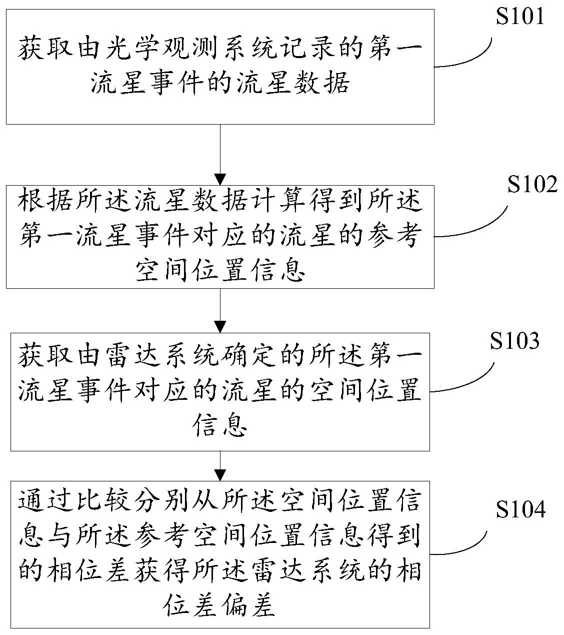
[0065] In Example 2, the spatial position of the meteor and the correction data of the radar system 120 are jointly determined by the optical observation system 110 and the correction data calculation device 100 .

[0066] image 3 As shown, the correction data calculation device 100 can perform the following steps: S301, acquire the meteor data of the first meteor event recorded by the optical observation system 110; S302, calculate and obtain the meteor corresponding to the first meteor event according to the meteor data. Reference spatial position information; S303, acquire the spatial position information of the meteor corresponding to the first meteor event determined by the radar system; S304, obtain by comparing the phase difference obtained from the spatial position information and the reference spatial position information respectively The phase difference bias of the radar system.

[0067] S301 Acquire the meteor data of the first meteor event recorded by the optica...


PUM


Abstract

The embodiment of the invention provides a phase correction method and a meteor position acquisition method, and the phase correction method is applied to phase difference correction of a plurality ofreceiving channels in an interference radar system. The method comprises the following steps: acquiring meteor data of a first meteor event recorded by an optical observation system; calculating reference spatial position information of meteors corresponding to the first meteor event according to the meteor data; acquiring the spatial position information of meteors corresponding to the first meteor event determined by a radar system; and obtaining a phase difference from the spatial position information and the reference spatial position information through comparison to obtain a phase difference deviation of the radar system. According to the embodiment of the invention, the meteor trajectory is recorded through the optical observation system, the accurate position of the meteor is calculated in combination with the trajectory data, and the correction parameters of the radar system are determined in combination with the position information of the same meteor recorded by the radar system to be corrected, so the phase correction precision of the radar system is improved.

Description

technical field [0001] The present application relates to the field of radar system phase correction, in particular, to a phase correction method and a meteor position acquisition method. Background technique [0002] The Earth's ionosphere is a region where the background neutral atmosphere is partially ionized, and the ionospheric inhomogeneity that appears therein is a structure in which the electron density is unevenly distributed. The inhomogeneity of the ionosphere can change the propagation path of radio waves, causing random and rapid fluctuations in the amplitude and phase of radio signals, resulting in the degradation of radio system performance. Radar is a common method for detecting ionospheric inhomogeneities. [0003] Radar emits radio wave signals, which will produce backscattered echoes when encountering inhomogeneous objects. By receiving the echo signal, the line-of-sight distance and moving speed of the uneven body can be obtained. When using multiple r...

Claims


Application Information

Patent Timeline
IPC IPC(8): G01S7/40G01S13/06G01S19/42
CPCG01S7/4026G01S7/4052G01S13/06G01S19/42G01S7/403G01S7/4034
Inventor 杨思朋武志陈文志李国主
Owner INST OF GEOLOGY & GEOPHYSICS CHINESE ACAD OF SCI
Why Eureka
Try Eureka