Dust collector and control method, device and system of brushless direct current motor

A brushless DC motor and control method technology are applied in the fields of vacuum cleaners, control devices for brushless DC motors, and control systems for brushless DC motors, and can solve problems such as long positioning time, N-S pole reverse error, and increased software code amount.

Inactive Publication Date: 2020-07-07
JIANGSU MIDEA CLEANING APPLIANCES +1
View PDF8 Cites 4 Cited by
  • Summary
  • Abstract
  • Description
  • Claims
  • Application Information

AI Technical Summary

Problems solved by technology

However, this method has the following disadvantages: 1) The positioning time is long, which is not suitable for the occasion where the motor is required to start quickly; 2) In order to reduce the positioning time or increase the positioning reliability, it is necessary to increase the PWM duty cycle during positioning, which will increase Large starting current increases power consumption, and in some occasions powered by batteries, it will reduce system efficiency; 3) There may be reverse rotation during positioning, which is not suitable for occasions that require motor startup without reverse rotation; 4) Jitter is prone to occur during positioning and abnormal noise
However, this method has the following disadvantages: 1) The 120° pulse positioning can not cover the full 360° rotor position, and there is a blind area, which leads to N-S pole reverse error; 2) The judgment process is more complicated, which increases the amount of software code and

Method used


Image

  • Dust collector and control method, device and system of brushless direct current motor
  • Dust collector and control method, device and system of brushless direct current motor
  • Dust collector and control method, device and system of brushless direct current motor

Examples


Embodiment Construction

[0081] Embodiments of the present invention are described in detail below, examples of which are shown in the drawings, wherein the same or similar reference numerals designate the same or similar elements or elements having the same or similar functions throughout. The embodiments described below by referring to the figures are exemplary and are intended to explain the present invention and should not be construed as limiting the present invention.

[0082] A rotor positioning method for a brushless DC motor, a non-transitory computer-readable storage medium, a rotor positioning device for a brushless DC motor, and a control system for a brushless DC motor according to embodiments of the present invention will be described below with reference to the accompanying drawings.

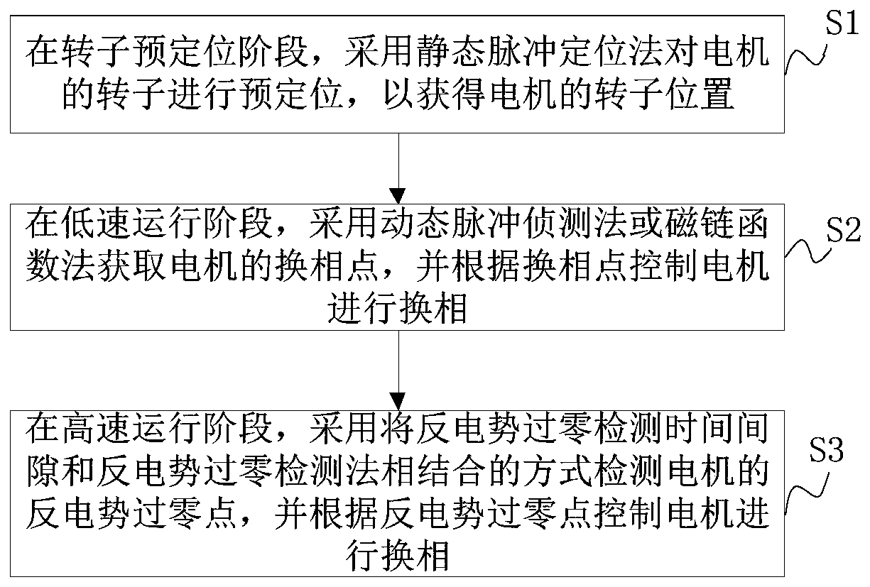
[0083] figure 1 is a flow chart of a control method for a brushless DC motor according to an embodiment of the present invention. Such as figure 1 As shown, the control method of the brushless DC motor ...


PUM


Abstract

The invention discloses a control method, device and system for a dust collector and a brushless direct current motor, and the method comprises that: in a rotor pre-positioning stage, the pre-positioning of a rotor of the motor is performed through employing a static pulse positioning method so as to obtain the position of the rotor of the motor; in a low-speed operation stage, a dynamic pulse detection method or a flux linkage function method is adopted to obtain a commutation point of the motor, and the motor is controlled to perform commutation according to the commutation point; and in themedium-high speed operation stage, the counter potential zero-crossing point of the motor is detected in a mode of combining the counter potential zero-crossing detection time interval and the counter potential zero-crossing detection method, and the motor is controlled to perform phase commutation according to the counter potential zero-crossing point. Therefore, the starting and positioning time of the motor can be greatly reduced, the motor is ensured not to rotate reversely during starting, abnormal sound and jitter during positioning are solved, accurate commutation of the motor in a low-speed operation stage can be realized, the reliability is high, a counter electromotive force zero-crossing point can be timely and accurately detected, and the motor is ensured to stably operate atan extremely high rotating speed.

Description

technical field [0001] The invention relates to the technical field of electric appliances, in particular to a control method of a brushless direct current motor, a control device of a brushless direct current motor, a control system of a brushless direct current motor and a vacuum cleaner. Background technique [0002] At present, in the technical field of sensorless drive control of brushless DC motors, the operation process of brushless DC motors may include a rotor pre-positioning stage, a low-speed operation stage, and a medium-high speed operation stage. [0003] In the related art, there are mainly two rotor positioning techniques when the motor is stationary and close to zero speed: forced pre-positioning method and pulse positioning method. Among them, the forced pre-positioning method does not consider the current position of the motor rotor, but energizes the fixed phase of the motor stator winding to make the motor rotor rotate to a predetermined position. Howev...

Claims


Application Information

Patent Timeline
IPC IPC(8): H02P6/182H02P21/18
CPCH02P6/182H02P21/18H02P2203/05H02P2203/03
Inventor 吴偏偏王浩东
Owner JIANGSU MIDEA CLEANING APPLIANCES
Why Eureka
Try Eureka