Clamping principle-based cylinder barrel boring equipment for ensuring machining quality

A technology of processing quality and cylinder, which is applied in the direction of metal processing equipment, drilling/drilling equipment, metal processing machinery parts, etc., can solve the problems of easy position deviation, affecting the quality of cylinder, and unfavorable processing operations, etc., to achieve increased The effect of large linkage

Active Publication Date: 2020-07-10
江苏重亚重工有限公司
View PDF11 Cites 4 Cited by
  • Summary
  • Abstract
  • Description
  • Claims
  • Application Information

AI Technical Summary

Problems solved by technology

[0003] The cylinder is composed of a cylinder barrel, an end cover, a piston, a piston rod, and a seal. The inner diameter of the cylinder barrel represents the output force of the cylinder. When the cylinder is working, the piston needs to slide reciprocally smoothly in the cylinder barrel. Therefore, the smoothness of the inner surface of the cylinder is very high. Usually, the cylinder is processed by boring, and the prefabricated hole on the workpiece is enlarged to a certain size with a rotating single-edged boring tool to achieve the required accuracy. Reduce the roughness of the inner surface of the cylinder. At present, when processing, the position of the boring tool is usually manually visually placed, and the cylinder is placed under the boring tool. Although tool setting is required before processing to determine the origin of the boring, However, the tool setting process is cumbersome, and the position of the tool may be offset during tool setting. It cannot guarantee the concentricity of the cy

Method used


Image

  • Clamping principle-based cylinder barrel boring equipment for ensuring machining quality
  • Clamping principle-based cylinder barrel boring equipment for ensuring machining quality
  • Clamping principle-based cylinder barrel boring equipment for ensuring machining quality

Examples


Embodiment Construction

[0024] The following will clearly and completely describe the technical solutions in the embodiments of the present invention with reference to the accompanying drawings in the embodiments of the present invention. Obviously, the described embodiments are only some, not all, embodiments of the present invention. Based on the embodiments of the present invention, all other embodiments obtained by persons of ordinary skill in the art without making creative efforts belong to the protection scope of the present invention.

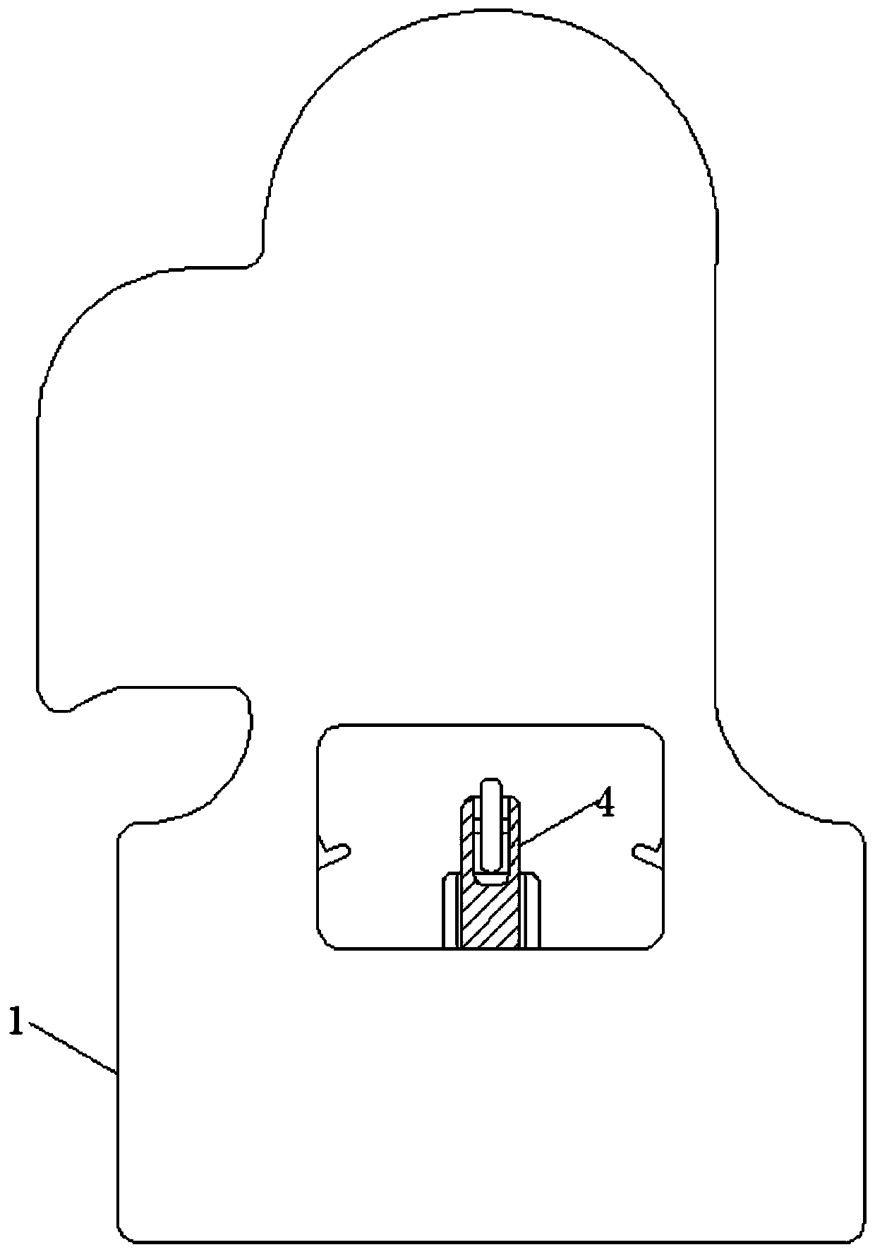
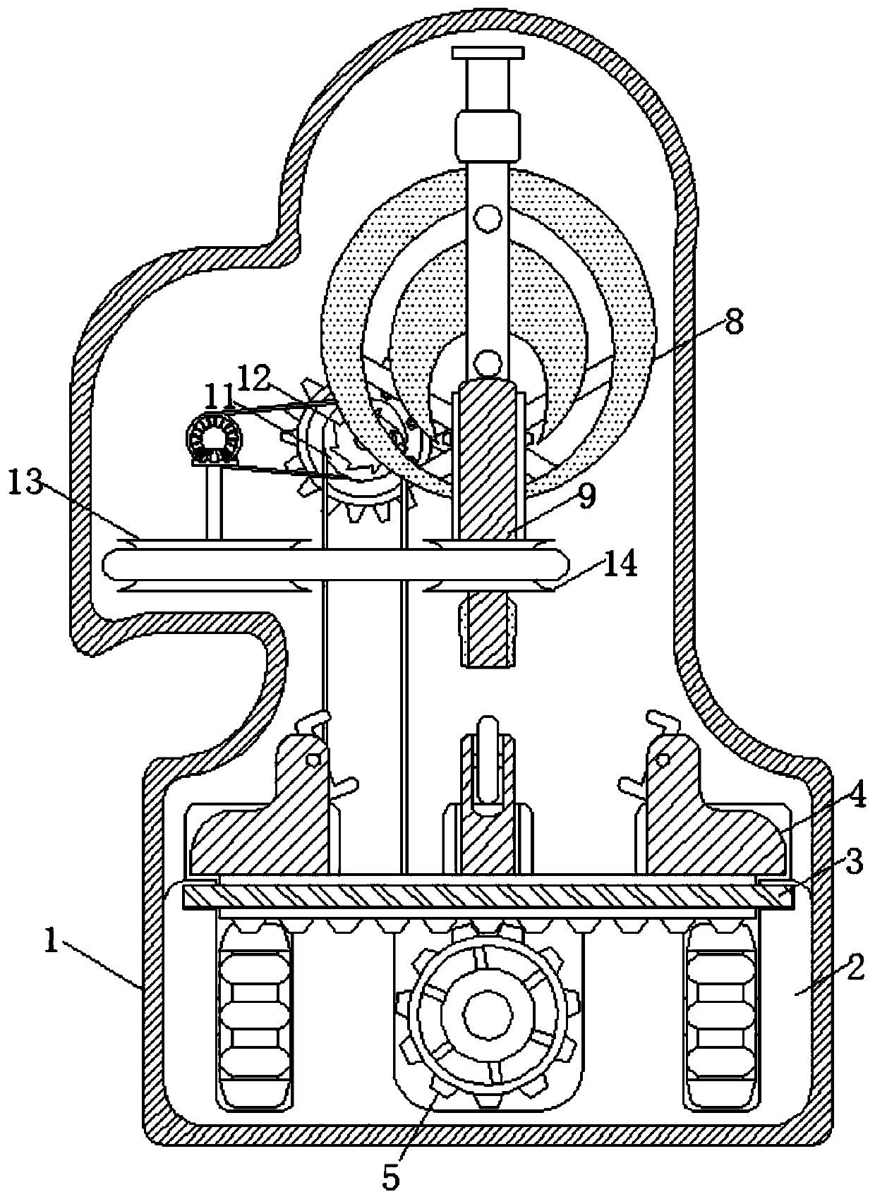
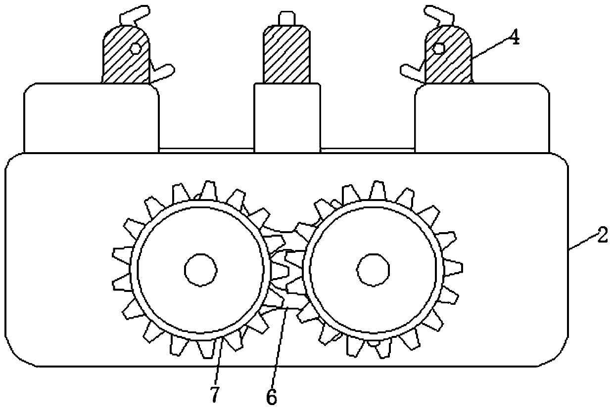
[0025] see Figure 1-6 , a cylinder boring equipment based on the clamping principle to ensure the processing quality, including a casing 1, the inside of the casing 1 is fixedly connected with a base 2, the surface of the base 2 is provided with a groove ring, and its size is suitable for the size of the toothed disc 3 Matching, there are two holes of the same size inside the base 2, and the two holes are symmetrically distributed with the central axis of the...


PUM


Abstract

The invention relates to the technical field of cylinders, and discloses a clamping principle-based cylinder barrel boring equipment for ensuring the machining quality. The equipment comprises a shell, wherein a base is fixedly connected in the shell; a second gear rotates to enable a first rotating disc to intermittently reciprocate, so as to provide a power source for the subsequent fixing operation, and thus the linkage among structures is increased; a first gear rotates to enable clamping blocks to be close to each other to clamp and fix a cylinder barrel between the clamping blocks, the position of the cylinder barrel is automatically adjusted, and the deviation between the center of the cylinder barrel and the center of a boring rod is avoided, so that the stability of the cylinder barrel is increased, and the cylinder barrel displaces during machining to ensure the machining quality; and a third rotating disc rotates to enable third gears mesh with each other to drive the thirdrotating disc to intermittently rotate by 360 degrees to provide a power source for the subsequent grinding operation; and a second rotating disc rotates to make the boring rod rotate at the high speed while the boring rod moves up and down, so that the boring rod gradually penetrates into a hole of the cylinder barrel to automatically finish the cylinder barrel.

Description

technical field [0001] The invention relates to the technical field of cylinders, in particular to a cylinder bore boring device based on a clamping principle to ensure processing quality. Background technique [0002] The cylinder is a cylindrical metal part that guides the piston to perform linear reciprocating motion in the cylinder. The air converts heat energy into mechanical energy through expansion in the engine cylinder; the gas is compressed by the piston in the compressor cylinder to increase the pressure, which is often used in printing, semiconductor, automation control, robotics and other fields. [0003] The cylinder is composed of a cylinder barrel, an end cover, a piston, a piston rod, and a seal. The inner diameter of the cylinder barrel represents the output force of the cylinder. When the cylinder is working, the piston needs to slide reciprocally smoothly in the cylinder barrel. Therefore, the smoothness of the inner surface of the cylinder is very high....

Claims


Application Information

Patent Timeline
IPC IPC(8): B23B41/00B23B41/12B23B47/14B23B47/18B23Q3/06
CPCB23B41/00B23B41/12B23Q3/062B23Q5/04B23Q5/22
Inventor 颜春玉
Owner 江苏重亚重工有限公司
Why Eureka
Try Eureka