Bearing gear ring gear stripe profiling cutting equipment and machining technology

A technology of profiling cutting and ring gear, which is applied in the field of bearing ring gear tooth pattern processing, can solve the problems of difficult tool movement, small bearing ring size, and high requirements for tool moving axes, so as to achieve stable and reliable processing and improve processing quality. , the effect of preventing interference problems

Pending Publication Date: 2020-07-10
WUXI YITONG PRECISION MACHINERY
View PDF1 Cites 7 Cited by
  • Summary
  • Abstract
  • Description
  • Claims
  • Application Information

AI Technical Summary

Problems solved by technology

[0003] When the existing profiling processing equipment processes the bearing ring gear, the product of the bearing ring gear is mostly fixed, and then the tool is moved until the tool processes a complete tooth structure on the side wall of the bearing ring. Although there is no major problem with the method, the requirements for the moving axis of the tool are relatively high, and some bearing ring products are small in size. When the tool moves around the bearing ring, it is easy to cause interference due to the short distance
[0004] A drilling machine gear processing equipm...

Method used


Image

  • Bearing gear ring gear stripe profiling cutting equipment and machining technology
  • Bearing gear ring gear stripe profiling cutting equipment and machining technology
  • Bearing gear ring gear stripe profiling cutting equipment and machining technology

Examples


Embodiment Construction

[0046] The following will clearly and completely describe the technical solutions in the embodiments of the present invention with reference to the accompanying drawings in the embodiments of the present invention. Obviously, the described embodiments are only some, not all, embodiments of the present invention.

[0047] In the description of the present invention, unless otherwise stated, the meaning of "plurality" is two or more; the terms "upper", "lower", "left", "right", "inner", "outer" , "front end", "rear end", "head", "tail", etc. indicate the orientation or positional relationship based on the orientation or positional relationship shown in the drawings, and are only for the convenience of describing the present invention and simplifying the description, rather than Nothing indicating or implying that a referenced device or element must have a particular orientation, be constructed, and operate in a particular orientation should therefore not be construed as limiting ...


PUM


Abstract

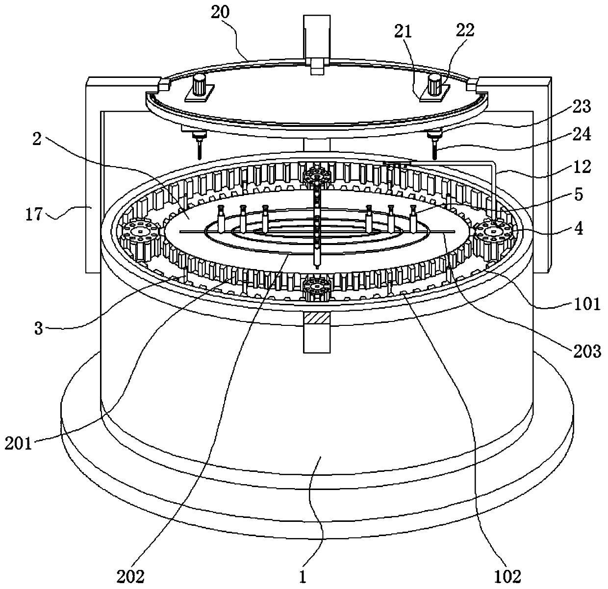
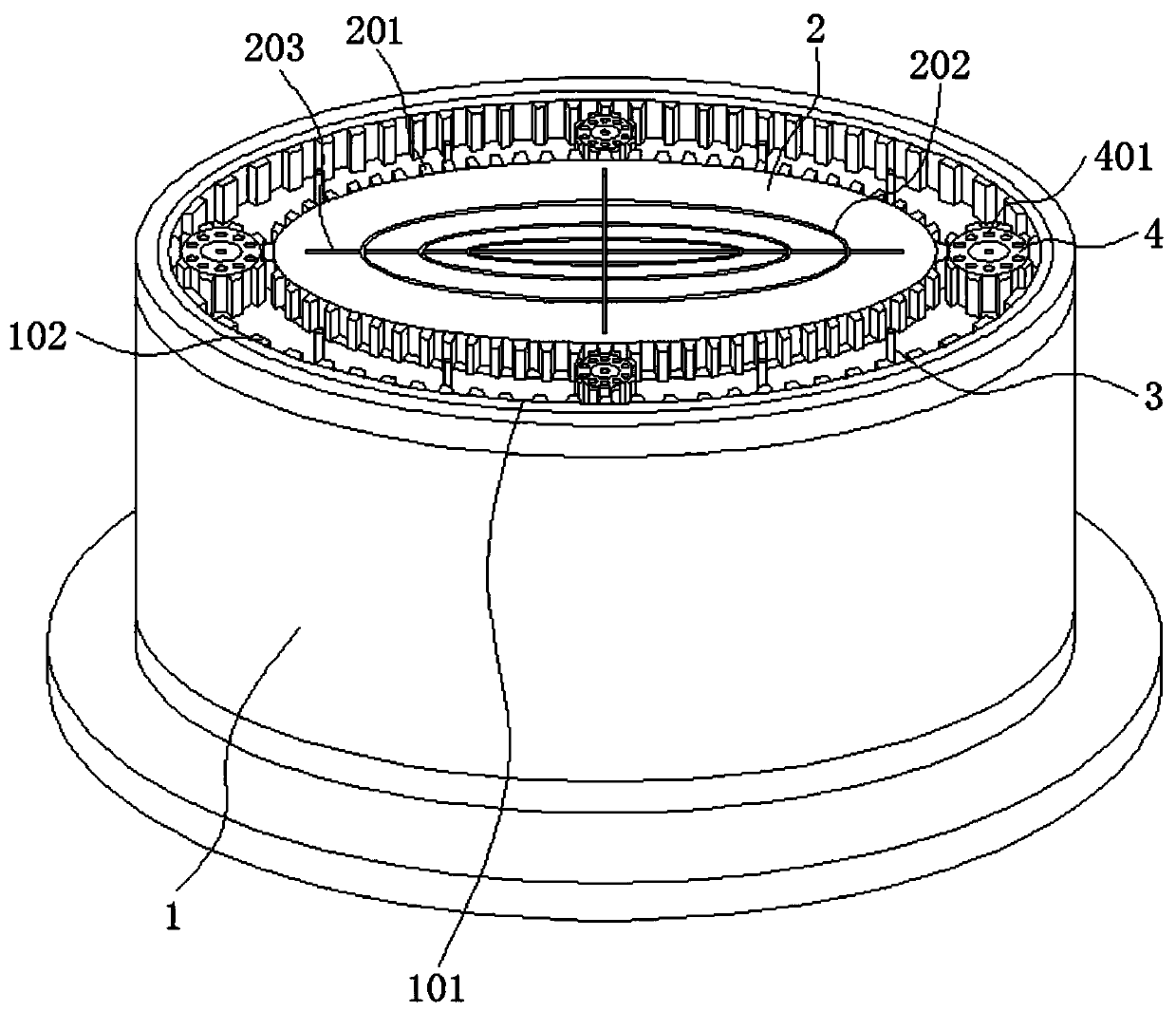
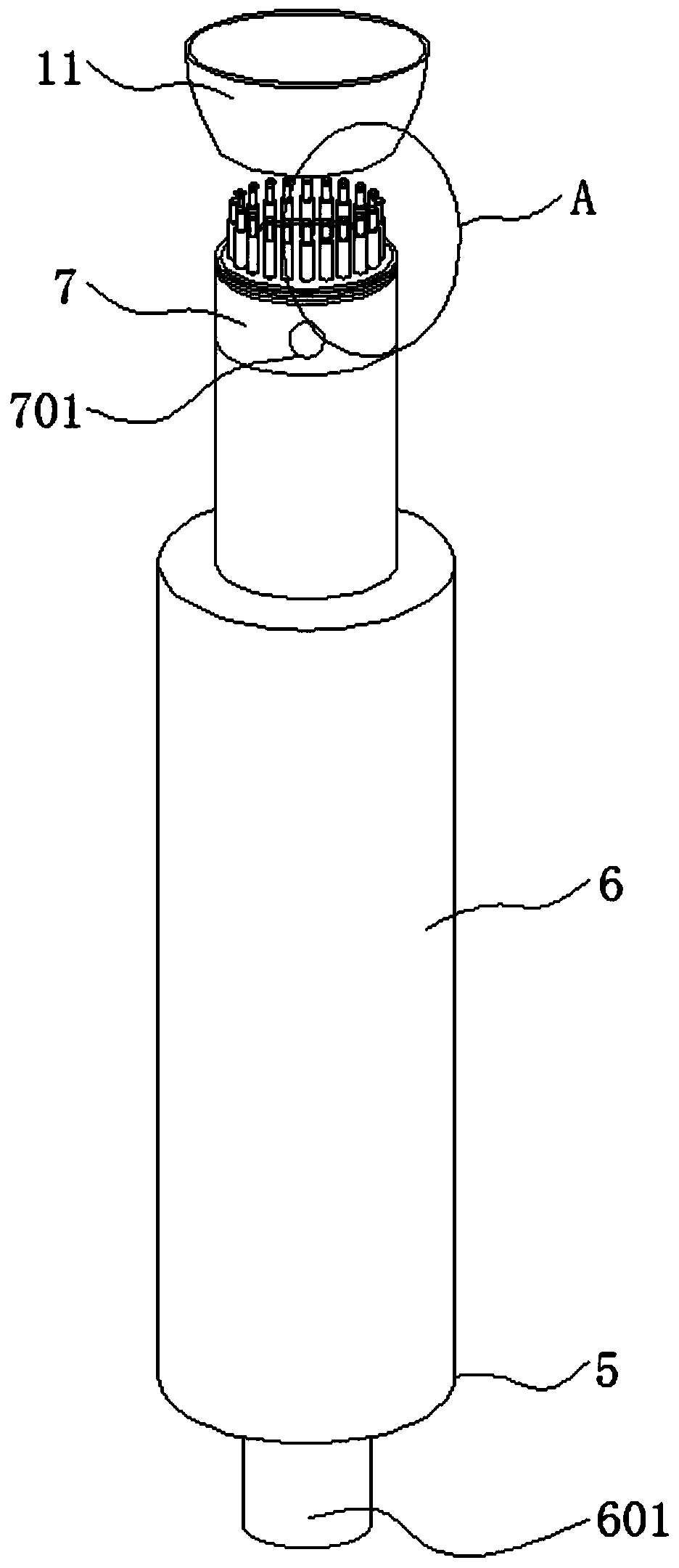
The invention discloses bearing gear ring gear stripe profiling cutting equipment and a machining technology, and relates to the technical field of bearing gear ring gear stripe machining. Specifically, a base, a rotation disc, a fixing mechanism, a scrap blowing mechanism, supports and a tool rotation disc are included. The edge of the upper surface of the base is provided with a ring groove. Therotation disc is rotationally matched to the center position of the upper surface of the base. The fixing mechanism is arranged above the base through an arc groove and a linear groove. The scrap blowing mechanism is inserted and connected in an inserting hole. The supports are welded to the position above the outer side wall of the base at equal intervals. The tool rotation disc is clamped and placed in a clamp groove. According to the bearing gear ring gear stripe profiling cutting equipment and the machining technology, a tool and a workpiece can move and are opposite in moving direction,during tooth-shaped structure machining is conducted on the workpiece, the problem of interference in the tool moving process can be effectively prevented, the workpiece tooth-shaped structure machining process is stably and reliably conducted, and the machining quality is effectively guaranteed.

Description

technical field [0001] The invention relates to the technical field of tooth profile processing of a bearing ring gear, in particular to a profiling cutting device and a processing technology for the tooth profile of a bearing ring gear. Background technique [0002] The bearing ring gear is the transmission bearing, which is composed of an eccentric mechanism, an inner gear ring and a transmission ring between the two. Its main function is to support the mechanical rotating body, reduce the friction coefficient during its movement, and ensure its rotation accuracy. In the production process of the ring, it needs to go through the tooth pattern processing, that is, it needs to use a special tool to profile the tooth structure, which requires the use of profiling processing equipment. [0003] When the existing profiling processing equipment processes the bearing ring gear, the product of the bearing ring gear is mostly fixed, and then the tool is moved until the tool process...

Claims


Application Information

Patent Timeline
IPC IPC(8): B23F5/00B23F23/06B23Q5/28B23Q11/00B08B5/02
CPCB08B5/02B23F5/00B23F23/06B23Q5/28B23Q11/005
Inventor 易阳
Owner WUXI YITONG PRECISION MACHINERY
Why Eureka
Try Eureka