
Polishing device and polishing process for inner ring and outer ring of bearing ferrule

A technology for bearing rings and inner and outer rings, which is applied in the polishing equipment and polishing technology field of inner and outer rings of bearing rings. It can solve the problems of inability to change, troublesome operation, synchronous grinding of bearing rings, etc., and achieve the effect of improving polishing efficiency and effect

Active Publication Date: 2020-07-10
WUXI YITONG PRECISION MACHINERY
View PDF6 Cites 4 Cited by
  • Summary
  • Abstract
  • Description
  • Claims
  • Application Information

AI Technical Summary

Problems solved by technology

[0003] Most of the existing equipment for polishing bearing rings first fix the bearing rings with fixtures, and then run the grinding tool to polish the bearing rings, that is, the clamping surface of the general bearing rings is fixed in advance , cannot be changed during processing, which leads to the need to turn the bearing ring when grinding the end faces of both ends of the bearing ring, and re-clamp the turned bearing ring, which is troublesome to operate
[0004] A bearing ring polishing and grinding system disclosed in the Chinese invention patent application publication specification CN108115512A, although the bearing ring polishing and grinding system solves the problem that it is difficult to perform synchronous grinding on the inner and outer circles of the bearing ring, however, The bearing ring polishing and grinding system cannot quickly realize the replacement of the clamping and fixing surface of the bearing ring during the grinding process

Method used


Image

  • Polishing device and polishing process for inner ring and outer ring of bearing ferrule
  • Polishing device and polishing process for inner ring and outer ring of bearing ferrule
  • Polishing device and polishing process for inner ring and outer ring of bearing ferrule

Examples


Embodiment Construction

[0050] The following will clearly and completely describe the technical solutions in the embodiments of the present invention with reference to the accompanying drawings in the embodiments of the present invention. Obviously, the described embodiments are only some, not all, embodiments of the present invention.

[0051] In the description of the present invention, unless otherwise stated, the meaning of "plurality" is two or more; the terms "upper", "lower", "left", "right", "inner", "outer" , "front end", "rear end", "head", "tail", etc. indicate the orientation or positional relationship based on the orientation or positional relationship shown in the drawings, and are only for the convenience of describing the present invention and simplifying the description, rather than Nothing indicating or implying that a referenced device or element must have a particular orientation, be constructed, and operate in a particular orientation should therefore not be construed as limiting ...


PUM


Abstract

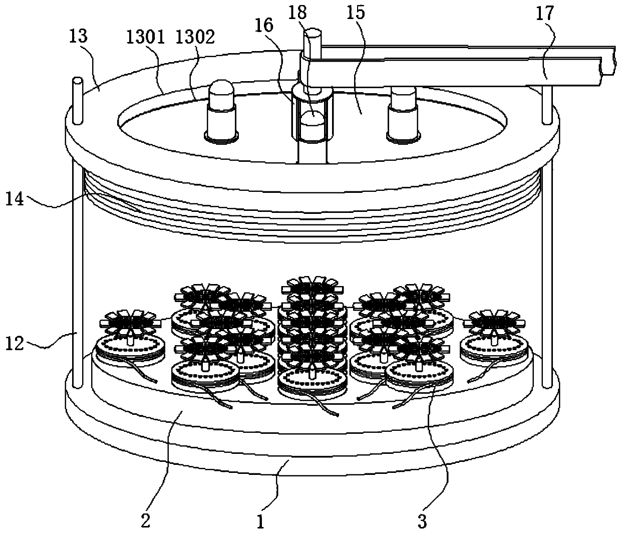
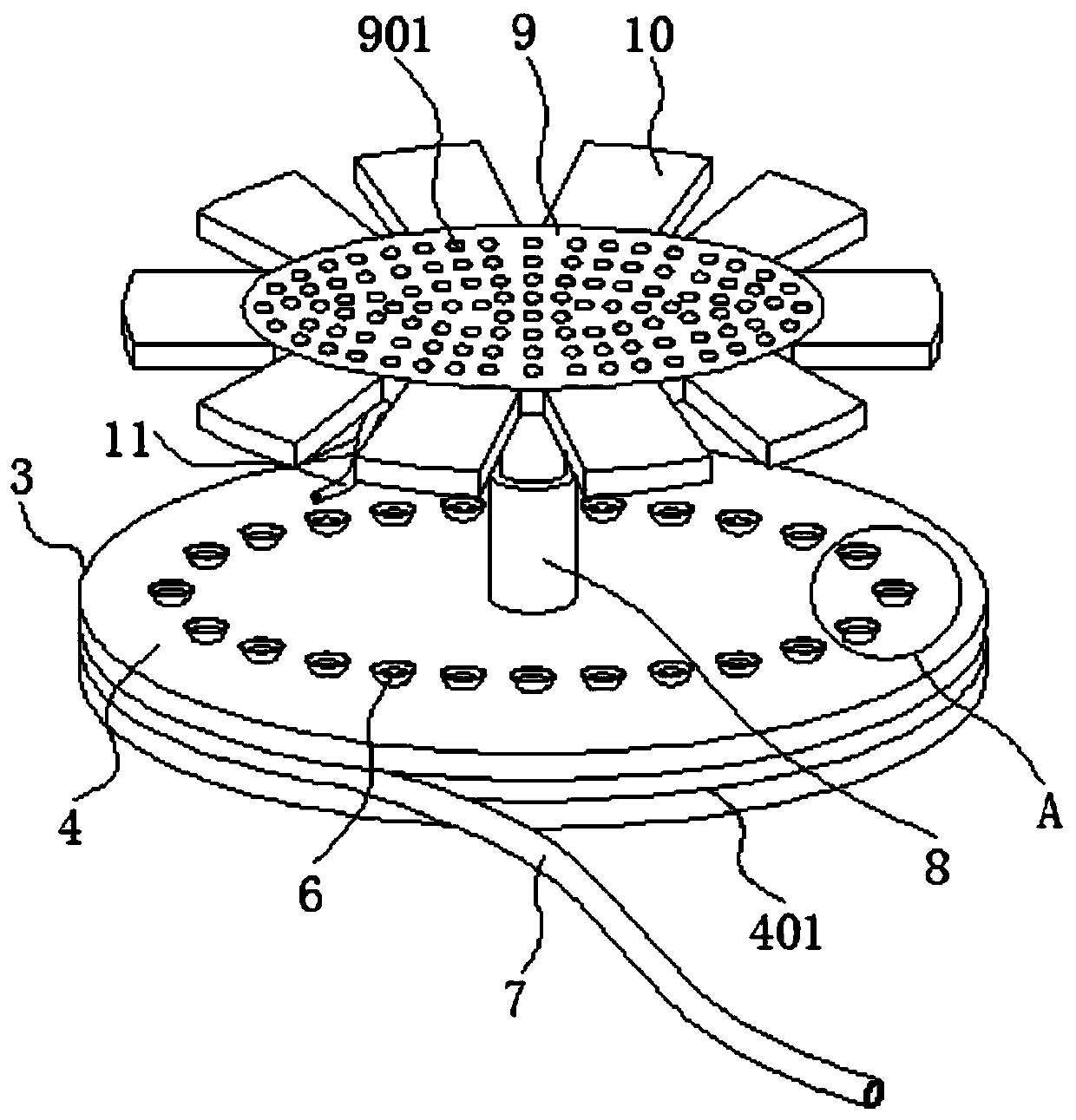
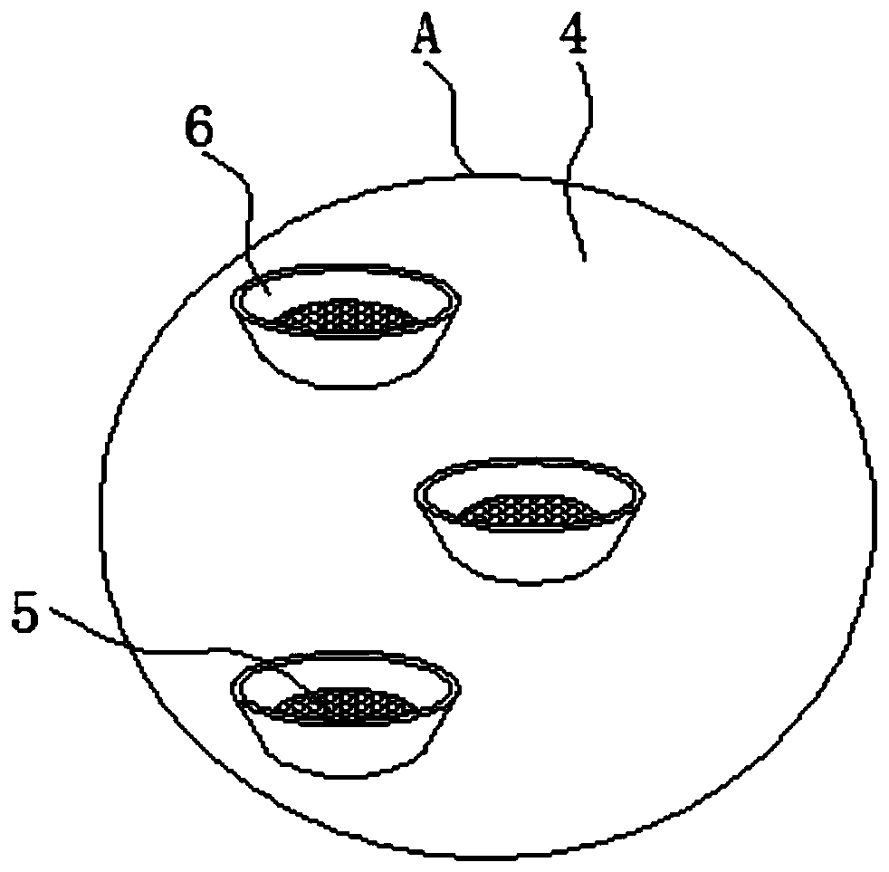
The invention discloses a polishing device and polishing process for an inner ring and outer ring of a bearing ferrule, and relates to the technical field of bearing ferrule processing devices. Concretely, the polishing device comprises a base plate, clamping mechanisms, a turntable and a grinding cover; a tray is welded to the upper surface of the base plate; the clamping mechanisms are evenly installed over the tray; the turntable is in running fit in an assembly groove; the outer side of a traction rod is in sleeved connection with a traction belt; polishing motors are arranged at the center of the inner side of the traction rod and the periphery of an outer ring of the traction rod; the center of the top face of the grinding cover is welded to the bottom end of a connecting shaft; andgas connecting pipes are fixed to the edge of the lower surface of a seat plate. According to the polishing process for the inner ring and outer ring of the bearing ferrule, a clamping fixing surfaceof the bearing ferrule can be directly changed during processing, and thereby, quick reverse clamping can be performed on the bearing ferrule, so that end faces of two ends of the bearing ferrule canbe polished, and the bearing ferrule does not need to be taken down and then clamped, which is convenient and quick.

Description

technical field [0001] The invention relates to the technical field of bearing ring processing equipment, in particular to polishing equipment and a polishing process for inner and outer rings of a bearing ring. Background technique [0002] The bearing ring is a ring-shaped part of a radial rolling bearing with one or several raceways. It is made of NitroMax steel (high-nitrogen stainless steel), standard bearing steel, ceramics, etc. The production steps are forging-heat treatment-grinding Processing, grinding is also called polishing, which refers to grinding the outer wall of the product until it is smooth and delicate, more beautiful and more precise in size. [0003] Most of the existing equipment for polishing bearing rings first fix the bearing rings with fixtures, and then run the grinding tool to polish the bearing rings, that is, the clamping surface of the general bearing rings is fixed in advance , cannot be changed during the machining process, which leads to ...

Claims


Application Information

Patent Timeline
Patent Type & Authority Applications(China)
IPC IPC(8): B24B1/00B24B29/04B24B41/02B24B41/06B24B47/12B24B47/22B24B55/06
CPCB24B29/04B24B1/00B24B41/06B24B55/06B24B47/22B24B47/12B24B41/02Y02P70/10
Inventor 易阳
Owner WUXI YITONG PRECISION MACHINERY
Learn More