Discharge tube manufacturing equipment for medical carbon dioxide laser

A carbon dioxide, laser technology, applied in lasers, laser parts, laser parts and other directions, can solve problems such as large errors and cumbersome

Active Publication Date: 2020-07-10
贝拉医疗科技(苏州)有限公司
View PDF11 Cites 1 Cited by
  • Summary
  • Abstract
  • Description
  • Claims
  • Application Information

AI Technical Summary

Problems solved by technology

[0003] Due to the characteristics of high hardness and high brittleness of glass or quartz materials, the discharge tubes processed with this material need to be tested for surface cracks and rigidity. Not only the error is large, but

Method used


Image

  • Discharge tube manufacturing equipment for medical carbon dioxide laser
  • Discharge tube manufacturing equipment for medical carbon dioxide laser
  • Discharge tube manufacturing equipment for medical carbon dioxide laser

Examples


Embodiment Construction

[0023] The following will clearly and completely describe the technical solutions in the embodiments of the present invention with reference to the accompanying drawings in the embodiments of the present invention. Obviously, the described embodiments are only some, not all, embodiments of the present invention. Based on the embodiments of the present invention, all other embodiments obtained by persons of ordinary skill in the art without making creative efforts belong to the protection scope of the present invention.

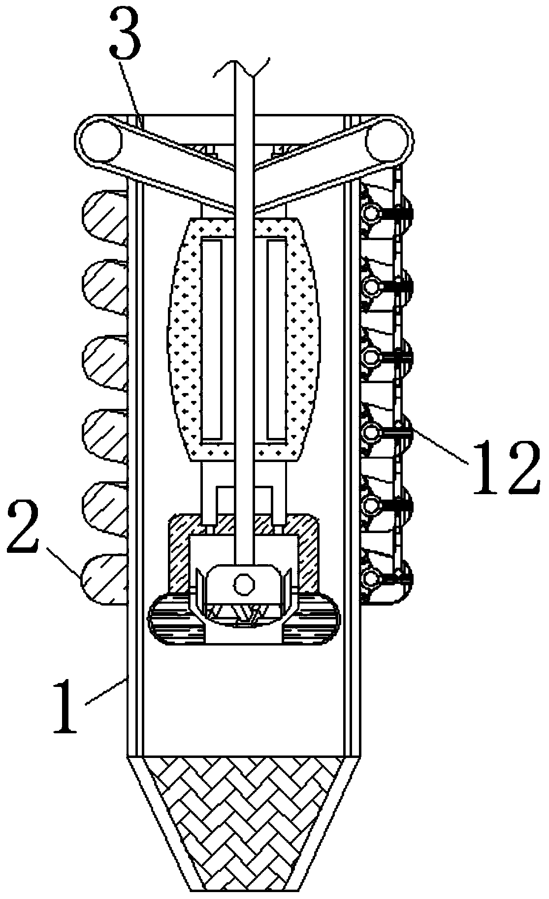
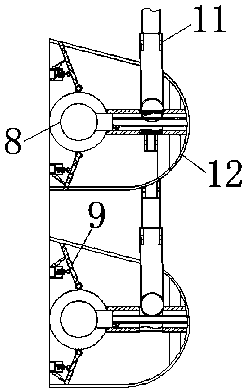
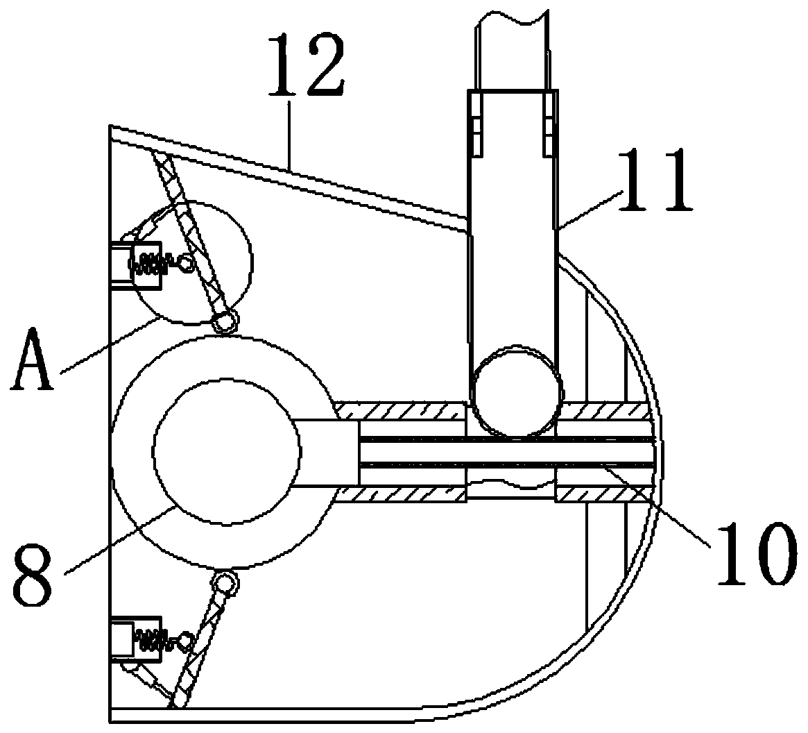
[0024] see Figure 1-6 , a carbon dioxide laser discharge tube manufacturing equipment for medical use, comprising a tube body 1, the surface of the tube body 1 is movably connected with a connecting sleeve 2, the surface of the connecting sleeve 2 is movably connected with a push rod 3, and the length of the connecting band 1 is the length of the tube body 1 3 / 4 of the length of the pipe body 1, and the push rod 3 is at the top of the pipe body 1, which is co...


PUM


Abstract

The invention relates to the technical field of carbon dioxide laser manufacturing, and discloses discharge tube manufacturing equipment for a medical carbon dioxide laser. The equipment comprises a tube body, wherein a connecting sleeve is movably connected to the surface of the tube body, a push rod is movably connected to the surface of the connecting sleeve, an air bag is fixedly connected tothe surface of the push rod, a sheltering and holding frame is fixedly connected to the position, located at the bottom of the air bag, of the surface of the push rod, a grinding disc is movably connected into the sheltering and holding frame through a compression spring, pressure applying wheels are movably connected into a connecting belt, adjusting pieces are movably connected to the surfaces of the pressure applying wheels, airflow pipes are movably connected into the pressure applying wheels, telescopic rods are movably connected to the surfaces of the airflow pipes, and the ends, away from the airflow pipes, of the telescopic rods are movably connected with spring wires. When the pressure applying wheels stably move on the surface of the tube body, the surface of the tube body is free of cracks, and otherwise, if one pressure applying wheel is sunken or raised, the surface of the tube body is uneven, so that the effect of detecting rigidity and cracks by using the working actionof polishing a discharge tube is achieved.

Description

technical field [0001] The invention relates to the technical field of carbon dioxide laser production, in particular to a medical carbon dioxide laser discharge tube production equipment. Background technique [0002] Carbon dioxide laser can be called "invisible person" because the laser wavelength it emits is 10.6 microns, and its "body" is in the infrared region, which cannot be detected by the naked eye. Its working mode is continuous and pulsed; carbon dioxide laser is a molecular laser. The main substance is carbon dioxide molecules; its components include discharge tubes and electrodes, among which the discharge tubes are made of glass or quartz materials. [0003] Due to the characteristics of high hardness and high brittleness of glass or quartz materials, the discharge tubes processed with this material need to be tested for surface cracks and rigidity. Not only the error is relatively large, but also after the discharge tube is touched manually, it needs to be w...

Claims


Application Information

Patent Timeline
IPC IPC(8): B24B5/06B24B5/35H01S3/03H01S3/036
CPCB24B5/06B24B5/35H01S3/03H01S3/036
Inventor 梁瑞倚
Owner 贝拉医疗科技(苏州)有限公司
Why Eureka
Try Eureka