
Part clamping and polishing machine equipment and working method thereof

A technology of machine equipment and parts, which is applied in the field of parts clamping and grinding machinery and equipment, can solve the problems of inconvenient clamping and difficult operation, and achieve the effect of convenient clamping

Inactive Publication Date: 2020-07-10
ANHUI SANLIAN UNIV
View PDF1 Cites 16 Cited by
  • Summary
  • Abstract
  • Description
  • Claims
  • Application Information

AI Technical Summary

Problems solved by technology

[0004] The purpose of the present invention is to provide a kind of parts clamping and grinding machine equipment and its working method, which is used to solve the problem that the existing clamping device clamps the inner and outer ends of the tubular parts in the vertical direction, which is inconvenient to clamp and difficult to operate. Difficult problem; the present invention squeezes the tubular parts in four directions up, down, left, and right through four arc-shaped clips, which is convenient for clamping, and the movable plate is pulled down, so that the movable plate slides up and down on the support rod to the machine. The upper end surface of the frame is fitted, and the movable plate moves downward, thereby driving several transparent PE plates on the louver to unfold; through the expansion of the transparent PE plate on the louver, it is convenient to cover the scraps during grinding and make them fall into the In the collection tank; grinding of tubular parts by clamping and rotating the circular holder

Method used


Image

  • Part clamping and polishing machine equipment and working method thereof
  • Part clamping and polishing machine equipment and working method thereof
  • Part clamping and polishing machine equipment and working method thereof

Examples


Embodiment Construction

[0025] The technical solutions of the present invention will be clearly and completely described below in conjunction with the embodiments. Apparently, the described embodiments are only some of the embodiments of the present invention, not all of them. Based on the embodiments of the present invention, all other embodiments obtained by persons of ordinary skill in the art without creative efforts fall within the protection scope of the present invention.

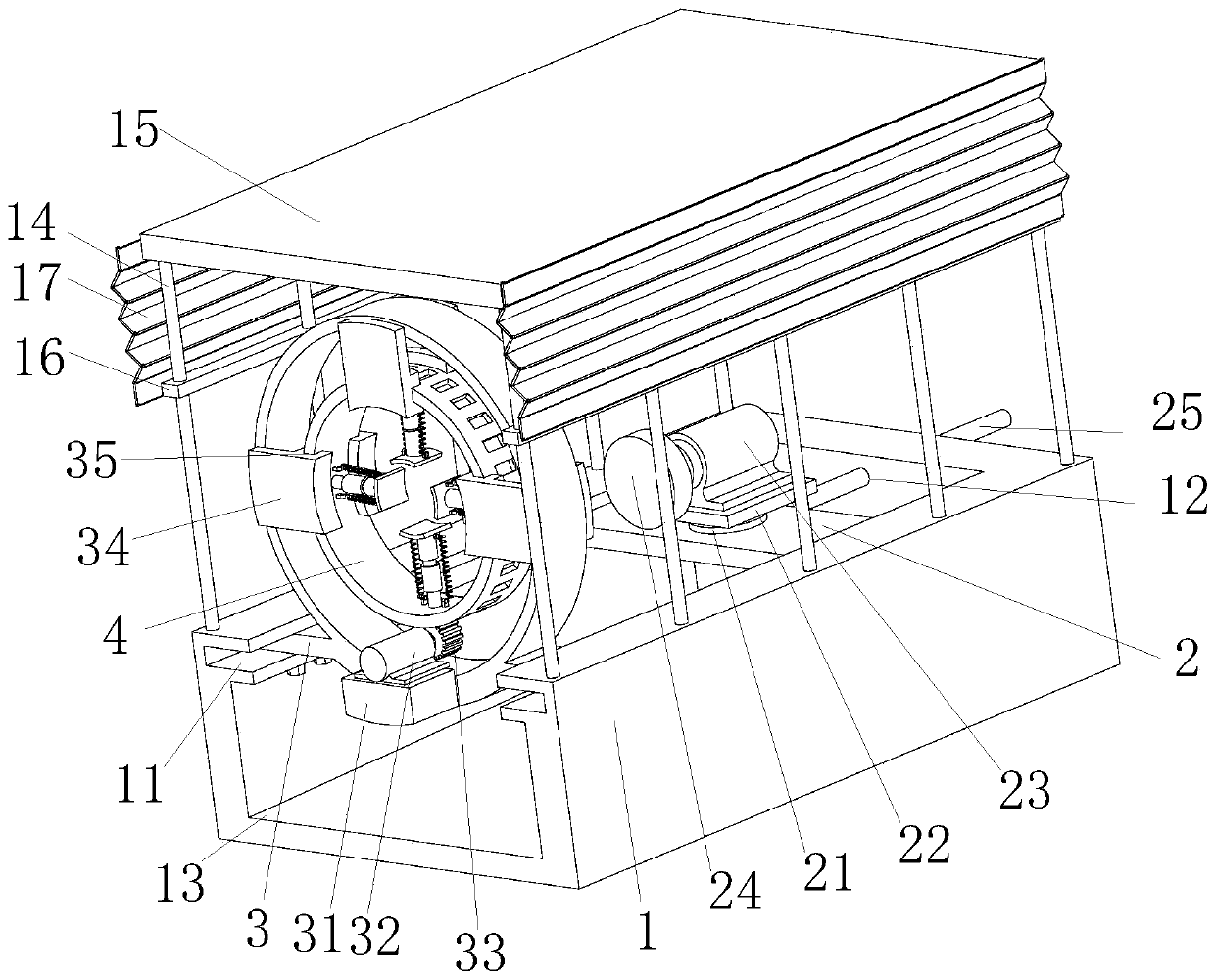
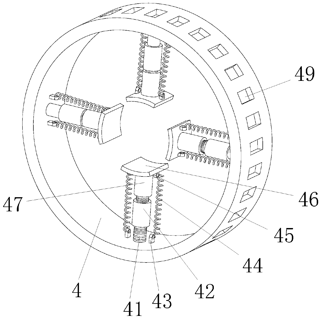
[0026] see Figure 1-5 As shown, a kind of parts clamping and grinding machine equipment includes a frame 1 and a fixed frame. The inner side walls of the frame 1 are symmetrically provided with chute 11, and the two ends of the bottom of the fixed frame 3 are respectively slidably inserted into two In the chute 11, the fixed frame 3 is fixedly connected with the chute 11 by bolts; a circular frame is installed on the fixed frame 3, and three fixed plates 34 are symmetrically installed on both sides of the circular frame. ...


PUM


Abstract

The invention discloses part clamping and polishing machine equipment and a working method thereof, which is used for solving the problems of inconvenient clamping and large operating difficulty whenan existing clamping device clamps the inner and outer ends of a tubular part in the perpendicular direction. The part clamping and polishing machine equipment comprises a machine frame and a fixed frame, sliding chutes are symmetrically formed in the two side walls of the interior of the machine frame, the two ends of the bottom of the fixed frame are inserted into the two sliding chutes in a sliding manner, and the fixed frame is fixedly connected with the sliding chutes through bolts. The tubular part is extruded in the up, down, left and right directions through four arc clamping pieces, clamping is convenient, movable plates are pulled downward, so the movable plates slide on supporting rods to be fit with the upper end face of the machine frame, the movable plates move downwards, andthus a plurality of transparent polyethylene (PE) plates on louver boards are driven to be unfolded; by unfolding the transparent PE plates on the louver boards, crushed materials are conveniently sheltered during polishing and fall into a collecting tank; and the tubular part is polished through clamping and rotation of a circular clamping holder.

Description

technical field [0001] The invention relates to the field of parts clamping and grinding equipment, in particular to a parts clamping and grinding machine and its working method. Background technique [0002] Generally, after the production of tubular parts, due to the long storage or transportation time, the surface of the inner and outer walls of the tubular parts will be oxidized and rusted. At the same time, there will be sand, welding slag and other sundries on the inner and outer walls of the tubular parts, which will affect the subsequent coating of anti-corrosion layer and other processing procedures, so the inner and outer walls of tubular parts generally need to be polished and derusted. The current rust removal method is generally to use sandpaper to remove rust, which requires manual hand-held sandpaper to rub the inside and outside of the tubular parts, but harmful dust will be generated during the rust removal process, and the working conditions of the workers ...

Claims


Application Information

Patent Timeline
Patent Type & Authority Applications(China)
IPC IPC(8): B24B27/033B24B5/40B24B5/04B24B5/35B24B41/06B24B41/02B24B47/12B24B55/12B24B55/00B24B1/00
CPCB24B1/00B24B5/04B24B5/35B24B5/40B24B27/033B24B41/02B24B41/067B24B47/12B24B55/00B24B55/12
Inventor 李杨刘国锋吴明明
Owner ANHUI SANLIAN UNIV
Features
  • Generate Ideas
  • Intellectual Property
  • Life Sciences
  • Materials
  • Tech Scout
  • Unparalleled Data Quality
  • Higher Quality Content
  • 60% Fewer Hallucinations
Learn More