
Molding equipment for high-rise building prefabricated wallboard part and machining method of molding equipment

A technology for high-rise buildings and molding equipment, which is applied to manufacturing tools, ceramic molding machines, mold auxiliary parts, etc. Pockmarked surface, better sealing effect

Active Publication Date: 2020-07-10
HEFEI NORMAL UNIV
View PDF6 Cites 1 Cited by
  • Summary
  • Abstract
  • Description
  • Claims
  • Application Information

AI Technical Summary

Problems solved by technology

[0006] Aiming at the deficiencies of the prior art, the present invention provides a forming equipment and processing method of prefabricated wall panels for high-rise buildings, which overcomes the deficiencies of the prior art, has a reasonable design and a compact structure, and aims to solve the problem of existing prefabricated wall panels. Part molding is usually carried out in an open groove mold, and the unloading of wallboard parts after forming is cumbersome, time-consuming and low in production efficiency.

Method used


Image

  • Molding equipment for high-rise building prefabricated wallboard part and machining method of molding equipment
  • Molding equipment for high-rise building prefabricated wallboard part and machining method of molding equipment
  • Molding equipment for high-rise building prefabricated wallboard part and machining method of molding equipment

Examples


Embodiment 1

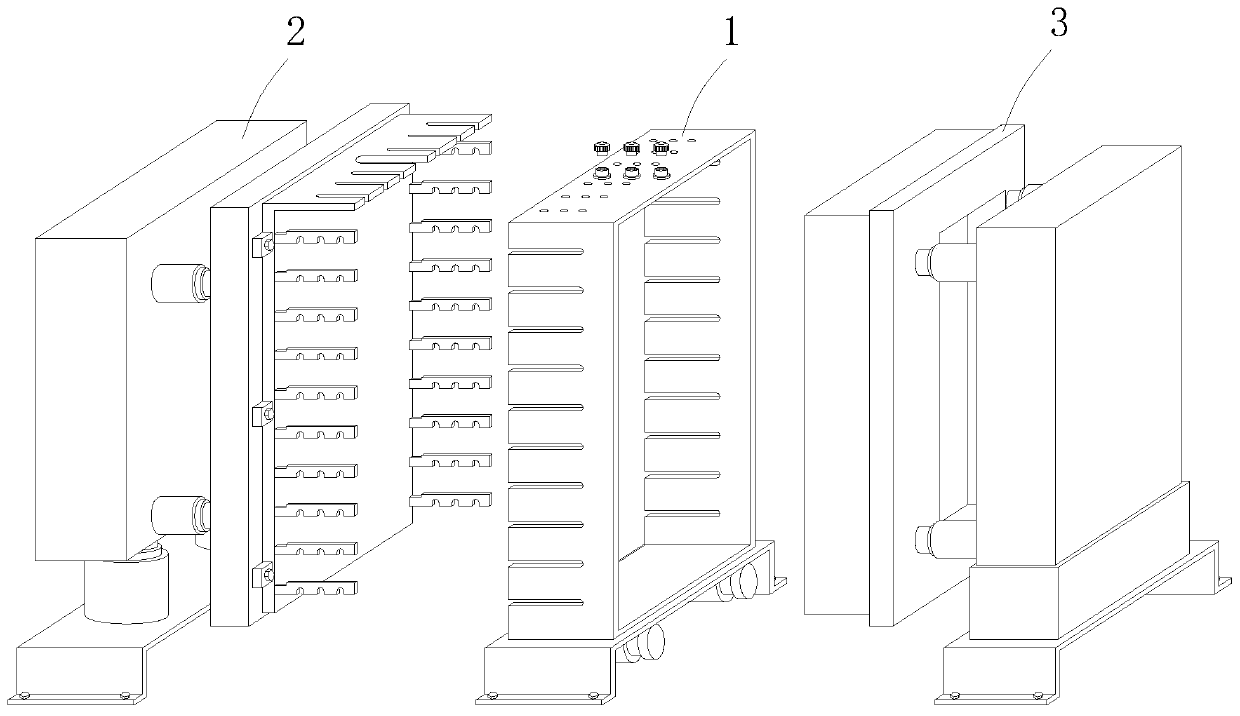
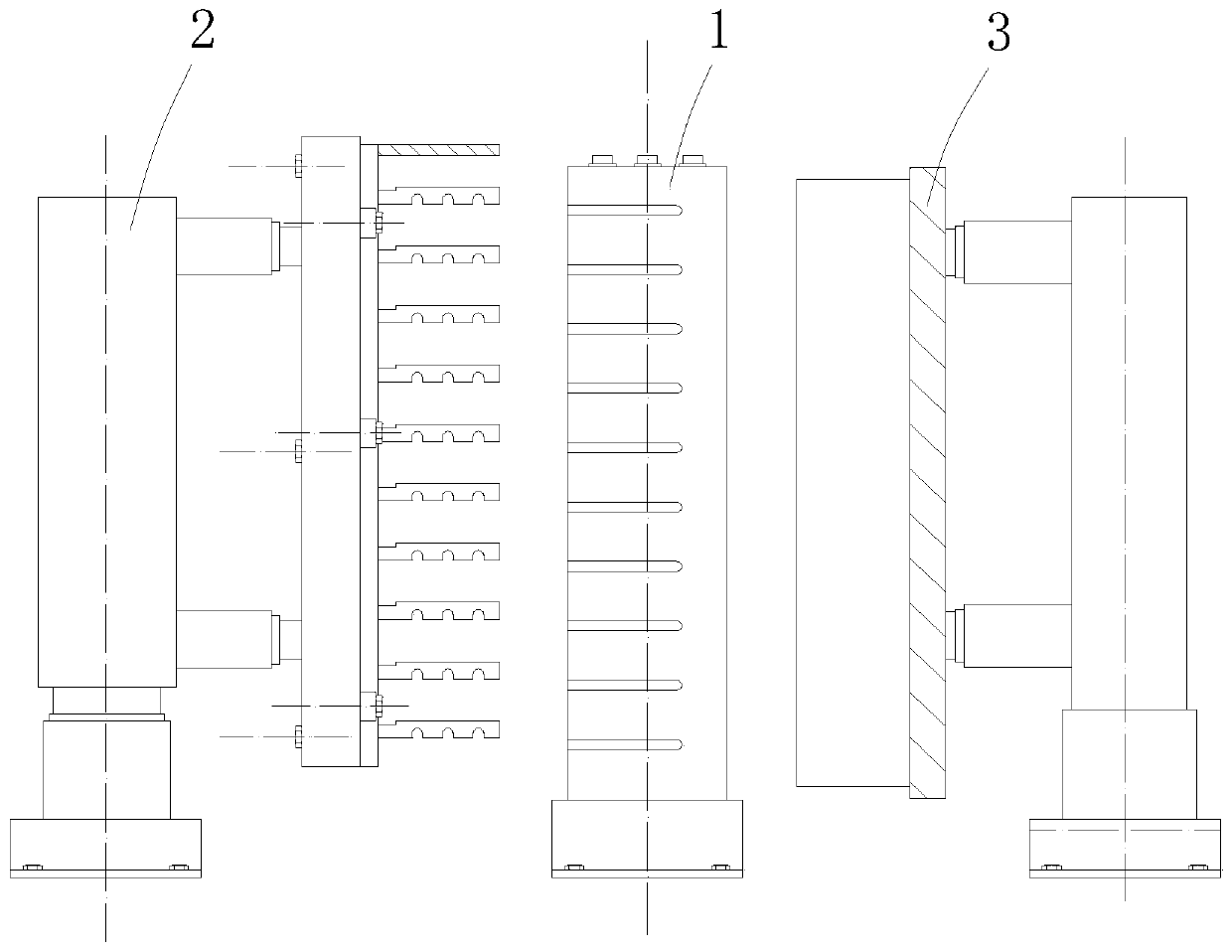
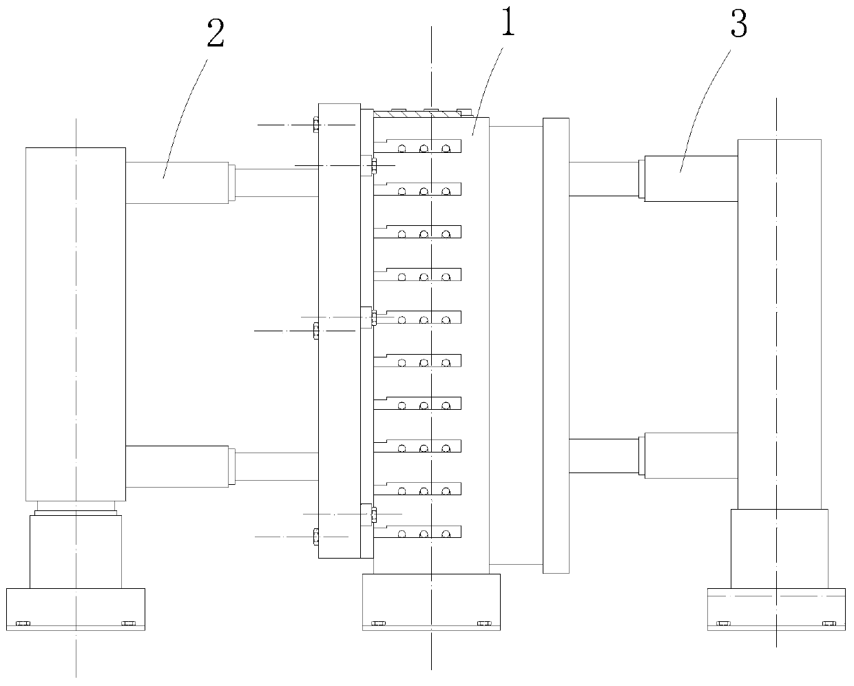
[0058] A forming equipment for prefabricated wall panels of high-rise buildings, such as Figure 1-3 As shown, it includes a structure mold 2, a cavity mold 1 and a bottom mold 3 arranged in parallel in a vertical direction;

[0059] In this embodiment, such as Figure 4 with 5 As shown, the structural mold 2 includes a base II 203 fixed on the ground by bolts, a lifting cylinder 202 is installed on the upper end of the base II 203, and a vertical cylinder seat I 201 is installed on the telescopic end of the lifting cylinder 202. The cylinder seat I 201 A structural mold base 205 is installed on the side close to the cavity mold 1 through multiple propelling cylinders I204, and a structural mold body 206 is detachably mounted on the other side of the structural mold base 205 by screws, and the structural mold body 206 is close to the cavity Two sets of side steel bar blocking plates 208 are installed symmetrically on the vertical edge of one side of the mold 1, and the bottom end ...

Embodiment 2

[0070] The difference between this embodiment and embodiment 1 lies in Picture 11 with 12 As shown, a cavity sealing module 4 for sealing a part of the casting cavity is detachably installed on the side of the structural mold base 205 close to the cavity mold body 101.

[0071] Such as Picture 11 As shown, a plurality of casting and bonding grooves 401 are provided on the side wall of the cavity-sealing module 4 close to the cavity mold body 101.

[0072] The cavity-sealing module 4 is set up to cooperate with the prefabricated wall panel a made of composite materials. Firstly, part of the panel is formed, and then the pouring slurry is replaced for adhesive pouring to ensure the production requirements of the prefabricated wall panel a. The setting of the pouring bonding groove 401 can make the first pouring part be formed with raised bonding columns, ensuring the close combination of the subsequent part of the slurry and the first forming part, and improving the molding quality ...

Embodiment 3

[0075] The present invention is based on the processing method of the high-rise building prefabricated wall panel forming equipment of the above-mentioned embodiment 1. The processing method includes the following steps:

[0076] Step 1. Clean the structure mold 2, the cavity mold 1 and the bottom mold 3, and coat the cavity surfaces of the structure mold 2, the cavity mold 1 and the bottom mold 3 with a release agent;

[0077] Step 2: Lay steel mesh a3 in the above-mentioned cavity mold 1;

[0078] Step 3: Push the structure mold 2 and the bottom mold 3 toward the cavity mold 1 to jointly construct a casting cavity;

[0079] Step 4. Quantitatively inject concrete slurry into the pouring cavity from the grouting port I 106, the grouting port II 107 and the grouting port III 108 above the cavity mold 1;

[0080] Step 5: The vibrating motor 105 at the lower part of the cavity mold 1 vibrates the concrete slurry in the pouring cavity, and the structural mold 2 and the bottom mold 3 continu...


PUM


Abstract

The invention relates to the technical field of building prefabricated parts, and provides molding equipment for a high-rise building prefabricated wallboard part and a machining method of the parts equipment. The molding equipment for the high-rise building prefabricated wallboard part and the machining method of the parts equipment aim to solve the problems that a large amount of time is consumed and the production efficiency is low due to the fact that disassembly is tedious after the wallboard part is formed due to the fact that an existing prefabricated wallboard part is usually molded inan open groove type mold. The molding equipment for the high-rise building prefabricated wallboard part comprises a structural mold, a cavity mold and a bottom mold which are vertically arranged in parallel in sequence; the structural mold comprises a base II fixed to the ground through bolts, a lifting air cylinder is arranged at the upper end of the base II, and an air cylinder base I which isvertically arranged is arranged at the telescopic end of the lifting air cylinder; and a structural mold base is arranged on the side, close to the cavity mold, of the air cylinder base I through a plurality of pushing air cylinders I, and a structural mold body is detachably arranged on the other side of the structural mold base through screws. The molding equipment for the high-rise building prefabricated wallboard part and the machining method of the parts equipment are particularly suitable for rapid high-quality molding of the high-rise building prefabricated wallboard part, and have highsocial use value and application prospect.

Description

Technical field [0001] The invention relates to the technical field of building prefabricated parts, in particular to a molding equipment for high-rise building prefabricated wall panels and a processing method thereof. Background technique [0002] Prefabricated wall panels refer to reinforced concrete slab-shaped components processed into prefabricated factories (fields) or construction sites for building assembly, referred to as wall panels or wall panels. With the development of society and the needs of urban high-rise construction, the use of precast concrete wall panels to construct prefabricated high-rise buildings can increase the degree of factory and mechanized construction, reduce on-site wet operations, save on-site labor, overcome seasonal effects, and shorten construction cycle. [0003] The existing prefabricated wall panels are usually formed in an open slot mold. After the wall panels are formed, unloading is cumbersome. The four side molds that make up the mold m...

Claims


Application Information

Patent Timeline
Patent Type & Authority Applications(China)
IPC IPC(8): B28B7/00B28B7/42B28B23/02B28B13/02B28B13/06B28B11/24
CPCB28B7/00B28B7/0002B28B7/0014B28B7/42B28B23/02B28B13/02B28B13/06B28B11/245B28B19/003B28B13/0275B28B23/024B28B1/087B28B7/0041
Inventor 曹烨君
Owner HEFEI NORMAL UNIV
Learn More