Continuous flow diverting energy dissipation type spillway and arc-shaped stilling pier

A stilling pier and spillway technology, applied in water conservancy projects, marine engineering, coastline protection, etc., can solve the problems of downstream river bank scour, achieve the effects of reducing the depth of scour pits, improving water flow conditions, and low cost

Pending Publication Date: 2020-07-10
TIANJIN CHENGJIAN UNIV
View PDF0 Cites 2 Cited by
  • Summary
  • Abstract
  • Description
  • Claims
  • Application Information

AI Technical Summary

Problems solved by technology

[0003] In order to solve the technical problems in the known technology, the present invention provides a continuous diversion energy dissipation spillway, arc-shaped force dissipation pier and energy dissipation unit, which can effectively solve the problem of high velocity water flow through the spillway by allowing water to impact each other in the spillway The problem of scouring the downstream river bank after deflecting the current

Method used


Image

  • Continuous flow diverting energy dissipation type spillway and arc-shaped stilling pier
  • Continuous flow diverting energy dissipation type spillway and arc-shaped stilling pier
  • Continuous flow diverting energy dissipation type spillway and arc-shaped stilling pier

Examples


Embodiment 1

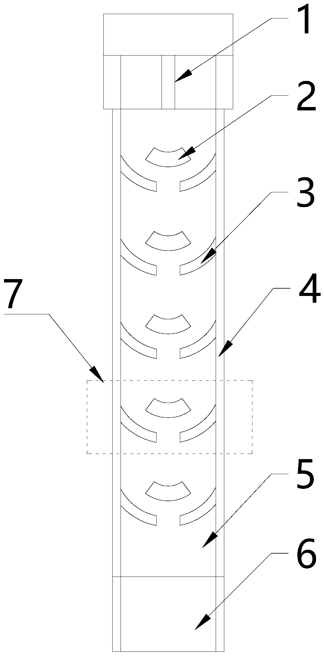
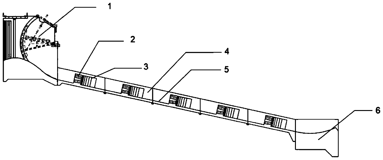
[0031] Embodiment 1: see attached Figure 1-2 , a continuous diversion and energy dissipation spillway, which consists of a diversion control section 1, an arc-shaped stilling pier 2, an arc-shaped diversion partition wall 3, a side wall 4, a bottom plate 5, and a deflecting energy dissipation section 6. The arc-shaped stilling pier 2, the arc-shaped diversion wall 3, the side wall 4 and the bottom plate 5 are integrally poured; the arc-shaped stilling pier 2 and the arc-shaped diversion wall 3 are both arc-shaped in the vertical water flow direction; The arc-shaped stilling pier 2 is located on the center line of the spillway, and the arc-shaped diversion wall 3 is symmetrically arranged on both sides of the downstream of the arc-shaped stilling pier 2; the width of the middle gap of a group of arc-shaped diversion walls 3 is the spillway 1 / 4 of the width; the intersection point of the left and right arc surfaces of the arc-shaped diversion partition wall 3 intersects with th...

Embodiment 2

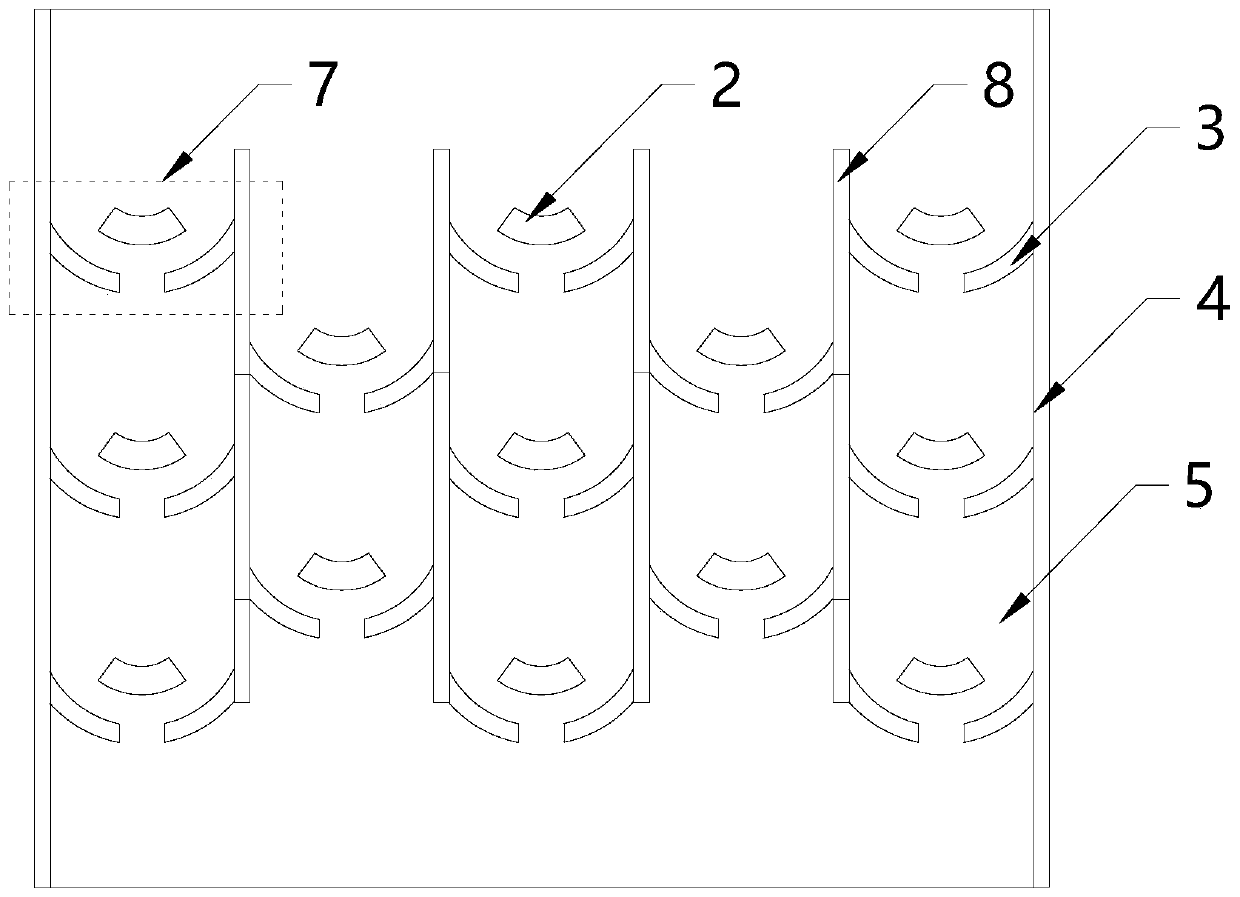
[0036] Embodiment 2: see attached image 3 , a continuous diversion and energy dissipation spillway, which is composed of arc-shaped stilling pier 2, arc-shaped diversion partition wall 3, side wall 4, partition wall 8 and floor 5; when the spillway is wide, a partition wall is added to it 8. Divide it evenly. In this embodiment, the spillway is divided into 5 spillways, and then an energy dissipation unit 7 is arranged in each spillway; 3. The side wall 4, the partition wall 8 and the bottom plate 5 are integrally poured; the width of the middle gap of each group of arc-shaped diversion partition walls 3 is 1 / 4 of the width of the flood discharge channel; the length of the partition wall 8 is less than the side wall 4, and the height It is equal to the side wall 4; the height of the arc-shaped diversion partition wall 3 is 1 / 3 of the height of the side wall 4 . Other structures are basically the same as in Embodiment 1.

[0037] Working principle: In this scheme, under the ...


PUM


Abstract

The invention relates to a continuous flow diverting energy dissipation type spillway, an arc-shaped stilling pier and an energy dissipation unit. The continuous flow diverting energy dissipation typespillway comprises arc-shaped stilling piers, arc-shaped flow diverting partition walls, a side wall and a bottom plate, the arc-shaped stilling piers, the arc-shaped flow diverting partition walls,the side wall and the bottom plate are integrally poured, the arc-shaped stilling piers and the arc-shaped flow diverting partition walls are arc-shaped in the direction perpendicular to the water flow direction, the arc-shaped stilling piers are located on the center line of the spillway, flow diverting holes are formed in pier bodies of the arc-shaped stilling piers, and the arc-shaped flow diverting partition walls are symmetrically arranged on the two downstream sides of the arc-shaped stilling piers correspondingly. According to the spillway, the structure is simple, the manufacturing cost is low, the number of energy dissipation sections can be automatically adjusted to be increased or decreased according to water flow conditions, the arc-shaped stilling piers are adopted to stop flow and dissipate energy, the arc-shaped flow diverting partition walls and the arc-shaped stilling piers are used in cooperation, the symmetrical arc-shaped flow diverting partition walls on the two sides guide water flow to generate concentrated counteraction energy dissipation with water flow from the arc-shaped stilling piers, the flow direction of fluid tends to be unified again, and the waterflow condition is improved.

Description

technical field [0001] The invention relates to the technical field of water conservancy engineering, in particular to flow channel flood discharge and energy dissipation, and in particular to a continuous diversion energy dissipation spillway and an arc-shaped force stilling pier. Background technique [0002] In order to vent the excess water of the reservoir, prevent floods from flooding the dam, ensure project safety, and meet the requirements of emptying the reservoir and flood control regulation, spillways are generally provided in water conservancy projects. However, most of the existing spillways only consider how to discharge flood quickly and in large quantities, and seldom consider the erosion of the downstream bank slope by water flow. When encountering a site with poor foundation conditions of the downstream riverbed (such as thick overburden, poor rock conditions, narrow riverbed or other important buildings arranged in the downstream riverway that need to be f...

Claims


Application Information

Patent Timeline
Patent Type & Authority Applications(China)
IPC IPC(8): E02B8/06
CPCE02B8/06
Inventor 李杰苏纪浩穆全平刘中宪
Owner TIANJIN CHENGJIAN UNIV
Why Eureka
Try Eureka