
High pressure common rail fuel delivery pump with adjustable pressure and flow rate

A high-pressure common rail, adjustable technology, used in fuel injection pumps, engine components, machines/engines, etc., can solve the problems of inability to adjust the pressure and flow of the fuel pump, poor controllability, inconvenience, etc., to avoid high frequency The effect of impact, prolonging life and reducing energy consumption

Pending Publication Date: 2020-07-10
北油电控燃油喷射系统(天津)有限公司
View PDF0 Cites 0 Cited by
  • Summary
  • Abstract
  • Description
  • Claims
  • Application Information

AI Technical Summary

Problems solved by technology

However, in this traditional ball valve structure, since the gap cross section between the steel ball and the inner wall of the valve body channel does not change with the compression depth of the overflow spring, the preload of the oil overflow spring can only be adjusted by tightening the screw plug 4. Furthermore, the adjustment of the opening pressure of the steel ball is realized, so the traditional ball valve structure cannot realize the adjustment of the pressure and flow rate of the oil pump for high-pressure common rail, and the controllability is poor
[0003] This shows that the above-mentioned existing high-pressure common rail oil delivery pump obviously still has inconvenience and defects in structure and use, and needs to be further improved urgently

Method used


Image

  • High pressure common rail fuel delivery pump with adjustable pressure and flow rate
  • High pressure common rail fuel delivery pump with adjustable pressure and flow rate
  • High pressure common rail fuel delivery pump with adjustable pressure and flow rate

Examples


Embodiment Construction

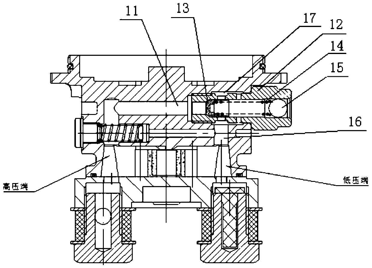
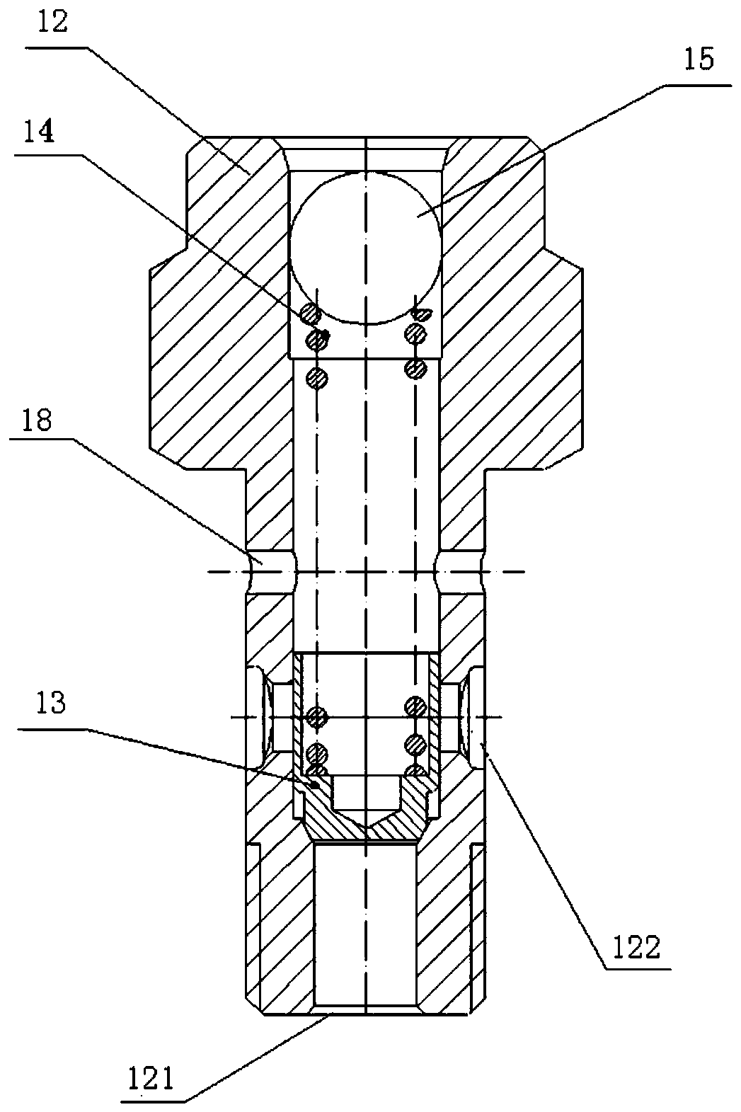
[0024] Refer to attached figure 2 with 3 As shown, the high-pressure common rail fuel delivery pump in this embodiment that can adjust the pressure and flow includes an adjusting slide valve arranged on the fuel passage 11 at the high-pressure end of the pump body. The adjusting slide valve includes a slide valve body 12 and a slide valve core 13. , Overflow spring 14 and fixed plug 15.

[0025] The slide valve body 12 is fixed on the high-pressure end fuel passage 11, and the slide valve body 12 is a hollow pipe, wherein an open end 121 of the hollow pipe communicates with the high-pressure end fuel passage 11, and the pipe wall of the hollow pipe An oil drain hole 122 is arranged on the top, and the oil drain hole 122 communicates with the fuel input channel 16 at the low pressure end of the pump body. The spool 13, overflow spring 14 and fixed plug 15 are sequentially arranged inside the hollow tube. The spool 13 is a cylindrical piston. , move axially along the hollow ...


PUM


Abstract

The invention discloses a high pressure common rail fuel delivery pump with the adjustable pressure and flow rate. The pump comprises a regulating slide valve arranged on a high pressure end fuel channel in a pump body. The regulating slide valve comprises a slide valve body, a slide valve element, an overflow spring and a retaining plug. The slide valve body is fixed to the high pressure end fuelchannel and is a hollow pipe, wherein one open end of the hollow pipe communicates with the high pressure end fuel channel, and an oil draining hole is formed in the pipe wall of the hollow pipe andcommunicates with a low pressure end fuel input channel in the pump body. The slide valve element, the overflow spring and the retaining plug are sequentially arranged inside the hollow pipe. The slide valve element is a cylindrical piston. The slide valve element moves axially along the hollow pipe under the double effects of fuel pressure and the overflow spring, the opening and closing action of the oil draining hole and the opening section area of the oil draining hole are controlled, and the fuel pressure and flow rate are adjusted. According to the high pressure common rail fuel deliverypump provided by the invention, by arranging the regulating slide valve on the high pressure end fuel channel of the pump body, the high pressure end fuel pressure and flow rate are adjusted and controlled, a traditional ball valve structure is successfully replaced, and the energy consumption is reduced.

Description

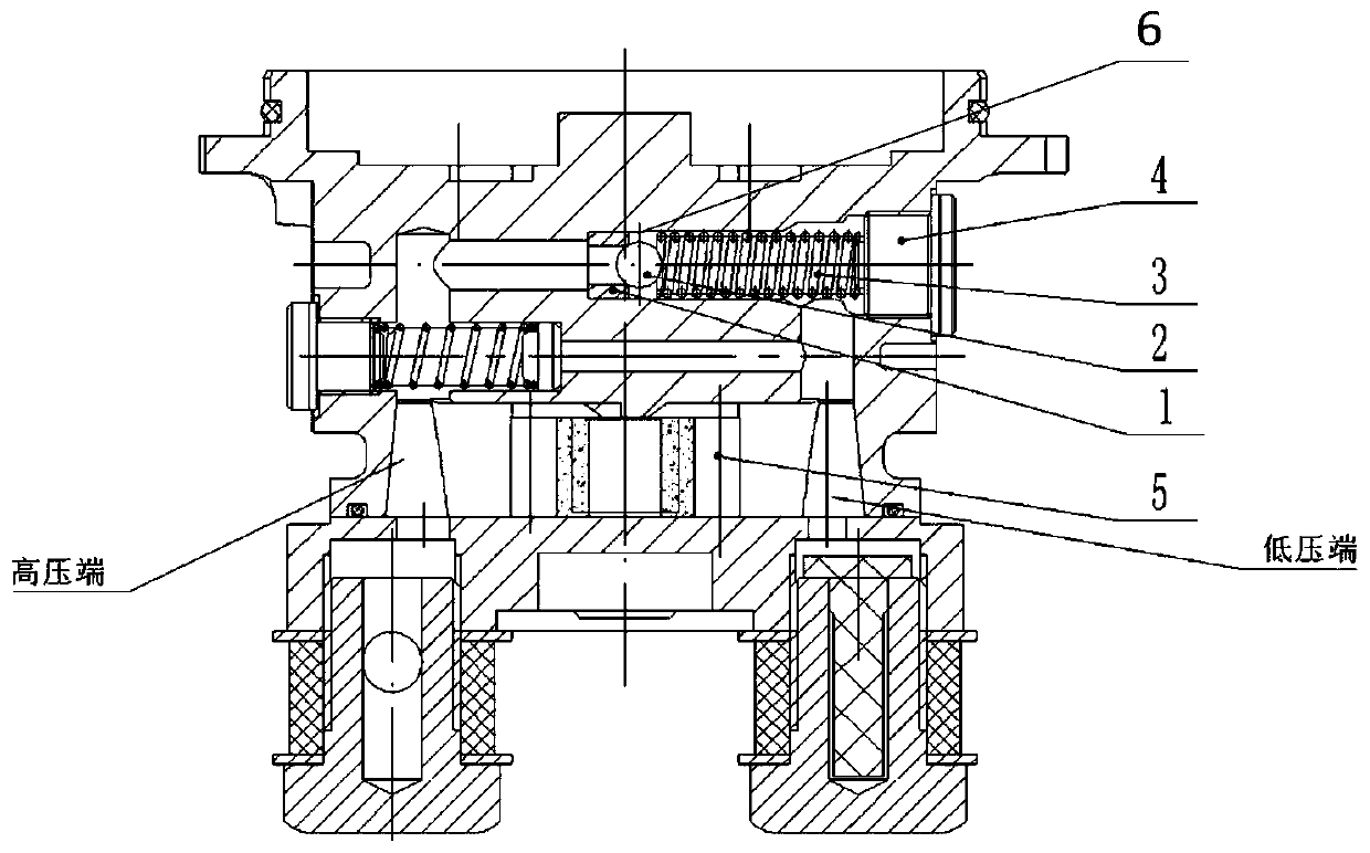
technical field [0001] The invention relates to the relevant technical field of a low-pressure fuel system of a fuel delivery pump for a high-pressure common rail, in particular to a fuel delivery pump for a high-pressure common rail with adjustable pressure and flow. Background technique [0002] The traditional high-pressure common rail pump uses a one-way safety valve structure to open and release pressure through the ball valve to achieve the purpose of protecting the safety of the system. as attached figure 1 As shown, the structure of the ball valve in the existing high-pressure common rail oil delivery pump includes: a valve seat 1, a steel ball 2, an overflow spring 3 and a screw plug 4. The fuel enters the high-pressure end from the low-pressure end through the rotation of two meshing gears 5. When the fuel pressure in the system is greater than the opening pressure of the ball valve structure, the ball valve opens, that is, the steel ball 2 is separated from the v...

Claims


Application Information

Patent Timeline
Patent Type & Authority Applications(China)
IPC IPC(8): F02M59/46F02M59/20
CPCF02M59/46F02M59/20
Inventor 张春雨
Owner 北油电控燃油喷射系统(天津)有限公司
Learn More