Supercharge Your Innovation With Domain-Expert AI Agents!

Composite heat exchanging device with grooved convex spherical surfaces and fins distributed alternately

A technology of heat exchange device and convex spherical surface, applied in lighting and heating equipment, heat transfer modification, heat exchange equipment, etc., can solve the problems of high flow rate, high heat flux density, small size, etc., and achieve enhanced flow heat transfer ability, improving the convective heat transfer coefficient, and the effect of good longitudinal disturbance ability

Inactive Publication Date: 2020-07-10
NANJING UNIV OF SCI & TECH
View PDF8 Cites 2 Cited by
  • Summary
  • Abstract
  • Description
  • Claims
  • Application Information

AI Technical Summary

Problems solved by technology

In addition, heating on one side can easily cause local heat transfer deterioration, resulting in thermal stratification, which is not conducive to heat transfer performance.
Due to the small size and high heat flux density of the cooling structure channel of the traditional engine combustion chamber wall, the enhanced heat transfer is mainly achieved by increasing the flow rate of the cooling medium and changing the cross-sectional size of the cooling channel. However, this will bring new problems, and in practice There are many restrictions in the process, such as the flow rate cannot be too high, too high flow rate means additional energy consumption, which will cause the performance of the engine to decline, and the influence of the size factor is also limited

Method used


Image

  • Composite heat exchanging device with grooved convex spherical surfaces and fins distributed alternately
  • Composite heat exchanging device with grooved convex spherical surfaces and fins distributed alternately
  • Composite heat exchanging device with grooved convex spherical surfaces and fins distributed alternately

Examples


Embodiment Construction

[0019] The present invention will be described in detail below in conjunction with the accompanying drawings and specific embodiments.

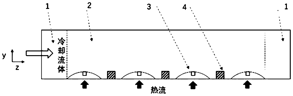
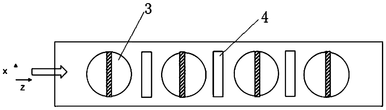
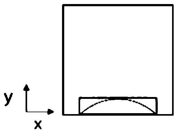
[0020] combine Figure 1-3 , a composite heat exchange device with grooved convex spherical surfaces and fins distributed in a distributed manner, including a plurality of convex spherical surfaces 3 and fins 4 arranged on the bottom surface of the cooling pipe, the plurality of convex spherical surfaces 3 and fins 4 Arranged at intervals in sequence, grooves are opened on the surface of the convex spherical surface 3 , the area where the convex spherical surface 3 and the fins 4 are provided is the flow disturbance area 2 , and the front and rear flow development area 1 .

[0021] Preferably, the opening direction of the groove is perpendicular to the flow direction of the fluid.

[0022] Preferably, the height of the convex spherical surface 3 is 10% of the equivalent diameter of the cooling pipe.

[0023] Preferably, the depth of the gro...


PUM


Abstract

The invention discloses a composite heat exchanging device with grooved convex spherical surfaces and fins distributed alternately. The device is characterized in that the device comprises the multiple convex spherical surfaces (3) and the multiple fins (4) which are arranged on the bottom surface of a cooling pipeline; the convex spherical surfaces (3) and the fins (4) are distributed alternately in sequence; and a groove is formed in the surface of each convex spherical surface (3). The device adopts a structure that the grooved convex spherical surfaces and the fins are distributed alternately. When a heat exchanging medium flows through the convex spherical surfaces and the grooves in a flow disturbance area (heated area), the fluid separates on the upper part of the convex sphericalsurfaces, the grooves break a flow boundary layer near the convex spherical surfaces, horizontal flow disturbance is formed while longitudinal disturbance is caused by the convex spherical surfaces, the heat exchange between the cold fluid in the center and the high-temperature fluid on a hot wall surface is accelerated, and, with better utilization of heat sinking of the fluid, the purpose of enhanced heat transfer is achieved while reduction of pressure drop is guaranteed.

Description

technical field [0001] The invention belongs to the technical field of heat exchangers, and in particular relates to a composite heat exchange device with grooved convex spherical surfaces and distributed distribution between fins. Background technique [0002] Ultra-high-sonic aircraft is facing huge thermal protection pressure. As the speed becomes faster and faster, the problem of thermal protection becomes more and more prominent. Under normal circumstances, the combustion chamber wall of a hypersonic scramjet engine is subjected to extremely high temperature and heat flux density, which can reach 0.8-160MW / m 2 . As the temperature of the engine combustion chamber is getting higher and the size of the engine is miniaturized, the size of the corresponding wall cooling channel will be smaller and smaller. Therefore, new cooling structures and devices that maintain a lower wall temperature must be studied and applied. To protect the walls of the engine combustion chamber ...

Claims


Application Information

Patent Timeline
Patent Type & Authority Applications(China)
IPC IPC(8): F28F1/40F28F13/02
CPCF28F1/40F28F13/02
Inventor 张小兵谢鹏勇
Owner NANJING UNIV OF SCI & TECH
Features
  • R&D
  • Intellectual Property
  • Life Sciences
  • Materials
  • Tech Scout
  • Unparalleled Data Quality
  • Higher Quality Content
  • 60% Fewer Hallucinations
Learn More