
Circuit board temperature distribution rapid test method based on small amount of measurement point data

A technology of temperature distribution and measuring point data, which is applied in the direction of electronic circuit testing, thermometers and thermometers using electric/magnetic elements that are directly sensitive to heat, and can solve problems such as low efficiency, large measurement errors, difficulty in measurement or large measurement errors, etc. problem, achieve the effect of reducing cost, improving test efficiency, and obtaining complete information

Inactive Publication Date: 2020-07-10
BEIHANG UNIV
View PDF7 Cites 4 Cited by
  • Summary
  • Abstract
  • Description
  • Claims
  • Application Information

AI Technical Summary

Problems solved by technology

[0005] 1) When the size of the circuit board and components is small, it is difficult to measure or the measurement error is large by using contact methods such as resistance thermometers or thermocouples;
[0006] 2) The measurement accuracy of the temperature distribution of the circuit board measured by the non-contact method is limited or the measurement error is relatively large;
[0007] 3) Most of the circuit board temperature test methods focus on the temperature test of individual components, but there is still a lack of test for the temperature distribution of the entire board;
[0008] 4) The simulation analysis method is used to determine the temperature distribution of the circuit board, which often has a long cycle and low efficiency, and is not suitable for application requirements such as rapid response required by engineering

Method used


Image

  • Circuit board temperature distribution rapid test method based on small amount of measurement point data
  • Circuit board temperature distribution rapid test method based on small amount of measurement point data
  • Circuit board temperature distribution rapid test method based on small amount of measurement point data

Examples


Embodiment Construction

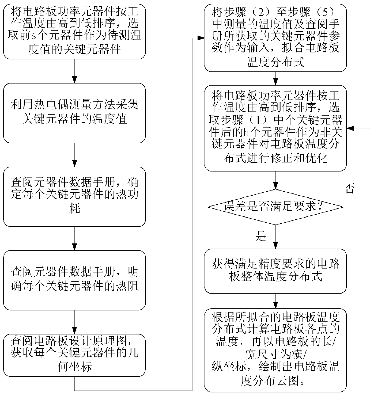
[0034] In order to make the features and advantages of the present invention more clearly understood, the following combination figure 1 The present invention is described in detail as follows:

[0035] The specific implementation steps of a kind of circuit board temperature distribution rapid test method based on a small amount of measuring point data of the present invention are:

[0036] Step (1): Sort the circuit board components in descending order of operating temperature, and select the first s components as key components for the temperature value to be measured.

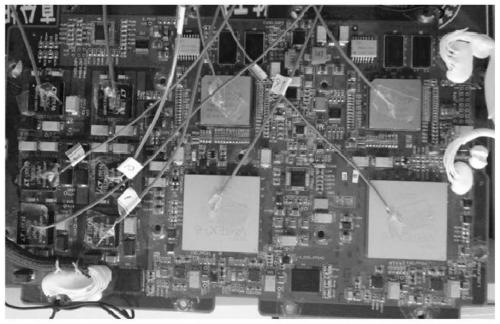
[0037] For the circuit board to be tested, considering the distribution of high-power and high-temperature components and the heat dissipation capability of the components, the components of the circuit board are sorted according to their operating temperature, and the first s components with higher temperature are selected as key components. In the example, the circuit board to be tested (such as figure...


PUM


Abstract

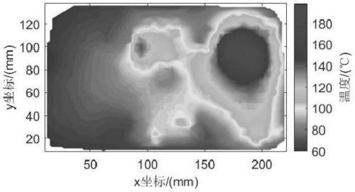
The invention provides a circuit board temperature distribution rapid test method based on a small amount of measurement point data, and the method comprises the steps: sorting circuit board power devices from high to low according to the working temperature, and selecting the first s devices as key components of a to-be-tested temperature value; acquiring temperature values of the key componentsby using a thermocouple measurement method; determining the thermal power consumption of each key component; determining the thermal resistance of each key device; obtaining geometric coordinates of each key device; fitting the temperature distribution of the circuit board by taking the parameters of the key devices as input; sorting the circuit board power devices from high to low according to the working temperature, selecting h devices after the s key devices as non-key devices, and collecting parameter data to optimize the temperature distribution of the circuit board; iterating the previous step until the precision of a temperature distribution calculation result of the circuit board meets the requirement; and calculating the temperature value of each point of the circuit board, and drawing a circuit board temperature distribution cloud chart.

Description

[0001] Technical field [0002] The invention provides a method for quickly testing the temperature distribution of a circuit board based on a small amount of measuring point data. This method measures the temperature of a small number of key components on the circuit board, and conducts high-precision analysis of its thermal resistance, thermal power consumption, position and other parameters as the main influencing factors of temperature, so as to quickly test the overall temperature distribution of the circuit board. The invention belongs to the temperature testing and analysis technology of electronic products (including circuit boards). This method can quickly test the temperature distribution of the entire circuit board on the basis of measuring the temperature values ​​of fewer components, and can be widely used in aviation, aerospace, weapons, ships, nuclear industries and other military fields as well as new energy, communication, rail transit, Thermal testing and ther...

Claims


Application Information

Patent Timeline
Patent Type & Authority Applications(China)
IPC IPC(8): G01R31/28G01K7/02
CPCG01R31/2849G01K7/02
Inventor 孙博姜福生明书君任羿钱诚杨德真冯强
Owner BEIHANG UNIV
Learn More