A cell stack structure of a flat tubular solid oxide fuel cell

A solid oxide and fuel cell technology, applied in the field of battery stack structure, can solve the problems of cathode side current collection difficulty, cathode current collection difficulty, long current path, etc., and achieve volumetric power density improvement, series-parallel flexibility, and strength improvement Effect

Active Publication Date: 2021-08-31
XI AN JIAOTONG UNIV
View PDF3 Cites 0 Cited by
  • Summary
  • Abstract
  • Description
  • Claims
  • Application Information

AI Technical Summary

Problems solved by technology

Disadvantages of tubular cells are the long current path and difficult current collection on the cathode side
[0005] Therefore, whether it is a tubular SOFC or a planar SOFC, there are problems of cathode current collection or sealing difficulties, and these problems are more significant when it is fabricated into a battery stack

Method used


Image

  • A cell stack structure of a flat tubular solid oxide fuel cell
  • A cell stack structure of a flat tubular solid oxide fuel cell
  • A cell stack structure of a flat tubular solid oxide fuel cell

Examples


Embodiment 1

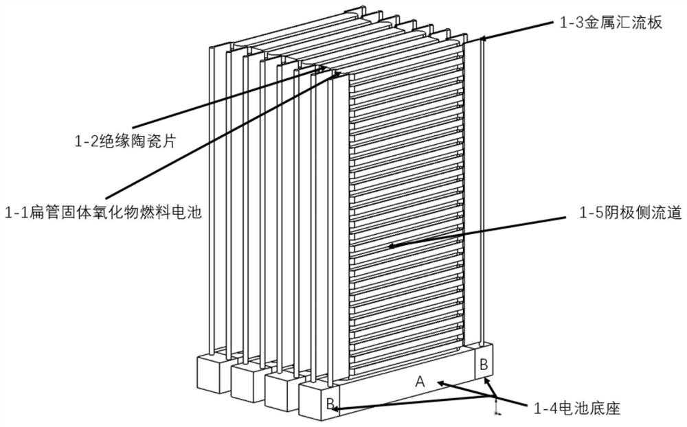
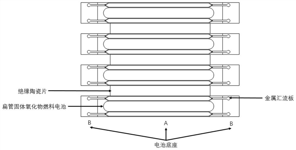
[0074] Stamping the metal manifold into figure 1 and figure 2 The structure shown will be image 3 and Figure 4 The metal-supported flat-tube solid oxide fuel cell with the structure shown is placed in the metal base A, and the battery and the base are fixed and sealed by brazing and welding. The metal manifold is placed on the cathodes on both sides, and the metal manifold base B and The metal bases A are insulated to form a battery unit. Insulating ceramic sheets are placed between the 30 single cells installed in this way, so that the metal bus plate is fixed to the cathode of the battery by elastic force. The anode and cathode of each single cell are respectively drawn out from the metal base A and the metal base B, such as figure 1 and figure 2 As shown, subsequent independent series-parallel connection.

Embodiment 2

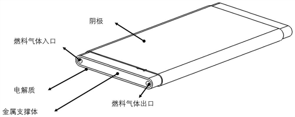
[0076] Stamping the metal manifold into Figure 7 The structure shown will be Figure 4 and Figure 5 The ceramic support flat tube solid oxide fuel cell with the structure shown is placed in the metal base A, the battery and the base are fixed and sealed with glass sealant, the metal manifold is placed on the cathodes on both sides, and the metal manifold base B is connected to the metal base A is insulated to form a battery unit. Place insulating ceramic sheets between the 50 single cells installed in this way, so that the metal bus plate is fixed to the cathode of the battery by elastic force. The anode current and cathode current of each single cell are respectively drawn from the metal base A and the metal base B, such as Figure 7 As shown, subsequent independent series-parallel connection.

Embodiment 3

[0078] Will Figure 5 and Figure 6 Prepare a layer of collector slurry on the cathode of the ceramic support flat tube solid oxide fuel cell with the structure shown, connect the metal collector plate to the cathode, and weld the metal collector plate on the base B. Put the battery into the metal base A, fix and seal the battery and the base with glass sealant, and insulate the metal manifold base B from the metal base A to form a battery unit. Put insulating ceramic sheets between the 15 single cells installed in this way, so that the metal bus plate is fixed to the cathode of the battery by elastic force. The anode current and cathode current of each single cell are respectively drawn from the metal base A and the metal base B, and then independently connected in series and parallel.


PUM


Abstract

The invention provides a cell stack structure of a flat tubular solid oxide fuel cell, the cell stack structure includes: a plurality of battery units and a plurality of insulating ceramic units, and a set of insulating ceramic units is arranged between each two insulating ceramic units. The above-mentioned battery unit; wherein, the battery unit includes: a metal manifold, a flat tube type solid oxide fuel, a base A and a base B; the base A and the base B are respectively used to fix the flat tube type solid oxide fuel and the metal manifold, and Base A and Base B are also used to conduct anodic and cathodic currents, respectively. Through the structure provided by the present invention, while solving the sealing problem, it also effectively solves the problems of how to make and arrange the flat tube solid oxide fuel cells with battery functional layers on both parallel sides into a battery stack, how to lead out and collect the two parallel sides The cathodic current problem.

Description

technical field [0001] The invention relates to the field of energy technology, in particular to a cell stack structure of a flat tube type solid oxide fuel cell. Background technique [0002] Solid oxide fuel cell (Solid oxide fuel cell abbreviated as SOFC) is a solid-state power generation device with high power generation efficiency, no noise and no pollution when working, and directly converts the chemical energy of the fuel into electrical energy without burning. Solid oxide fuel cells mainly include three functional layers: anode, electrolyte, and cathode. [0003] Currently, there are two basic structures of the SOFC structure, the tube type and the planar type. The biggest difference between the two lies in whether the direction of current collection and conduction is perpendicular to the direction of the electrolyte film or parallel to the direction of the electrolyte film. The advantages of flat-plate fuel cells are that the current path is small, the power densi...

Claims


Application Information

Patent Timeline
Patent Type & Authority Patents(China)
IPC IPC(8): H01M8/00H01M8/0271H01M8/04007H01M8/243H01M8/2457
CPCH01M8/004H01M8/0271H01M8/04067H01M8/243H01M8/2457Y02E60/50Y02P70/50
Inventor 李成新康思远李甲鸿李长久张山林
Owner XI AN JIAOTONG UNIV
Why Eureka
Try Eureka