
Underground continuous wall reinforcement cage hoisting method in height-limited area

A technology for hoisting underground diaphragm walls and steel cages, which is applied to sheet pile walls, buildings, cranes, etc., can solve the problems of poor quality control of underground diaphragm walls, increased exposure time of groove walls, and poor integrity of steel cages 4. The effect of speeding up the placement and construction progress, reducing the number of hoisting and welding, and the number of mechanical trips

Active Publication Date: 2020-07-14
SHENZHEN GONGKAN GEOTECHN GRP
View PDF5 Cites 0 Cited by
  • Summary
  • Abstract
  • Description
  • Claims
  • Application Information

AI Technical Summary

Problems solved by technology

[0005] 1. Many times of hoisting, welding and lengthening, time-consuming and labor-intensive, increased cost and poor integrity of the reinforcement cage 4;
[0006] 2. If the reinforcement cage 4 is placed for a long time, the exposure time of the groove wall will increase if it is too long, and it is easy to cause the collapse of the groove wall, mud in the cage body, excessive sediment, etc., which is unfavorable for the control of the construction quality of the underground diaphragm wall.
[0007] For example, in the construction of an underground diaphragm wall in a project in Shenzhen, the high-voltage wires on the wall are located at a height of 12m above the ground. According to the requirements of the specification, a safety distance of 5m must be ensured for hoisting operations below the high-voltage wires. The traditional segmented hoisting tool 3 occupies a space of 3.5m. Then the section length that can be manufactured by the theoretical reinforcement cage 4 is only 3.5m

Method used


Image

  • Underground continuous wall reinforcement cage hoisting method in height-limited area
  • Underground continuous wall reinforcement cage hoisting method in height-limited area

Examples


Embodiment Construction

[0058]The technical solutions of the present invention will be clearly and completely described below in conjunction with the accompanying drawings. Apparently, the described embodiments are some of the embodiments of the present invention, but not all of them. Based on the embodiments of the present invention, all other embodiments obtained by persons of ordinary skill in the art without making creative efforts belong to the protection scope of the present invention.

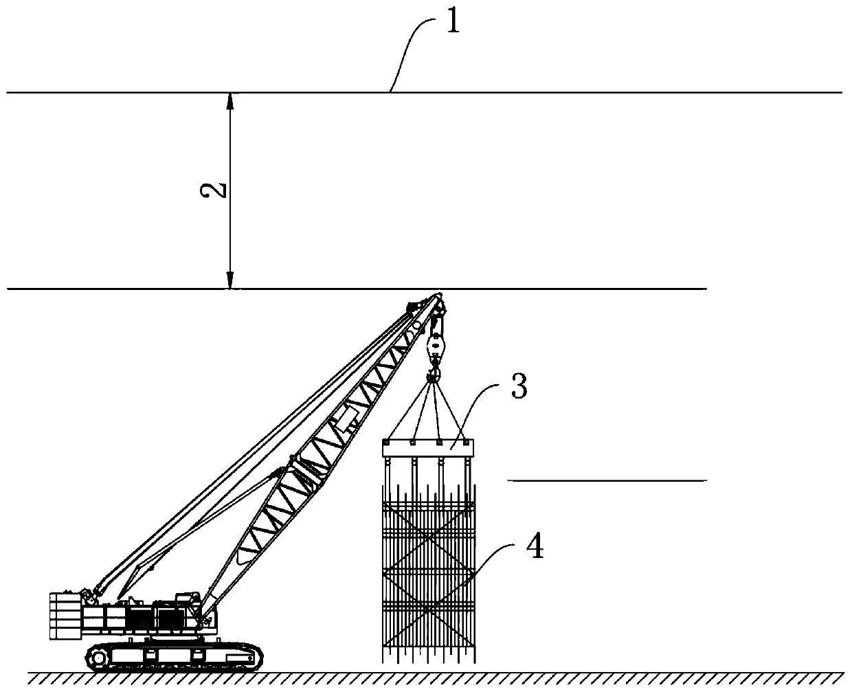
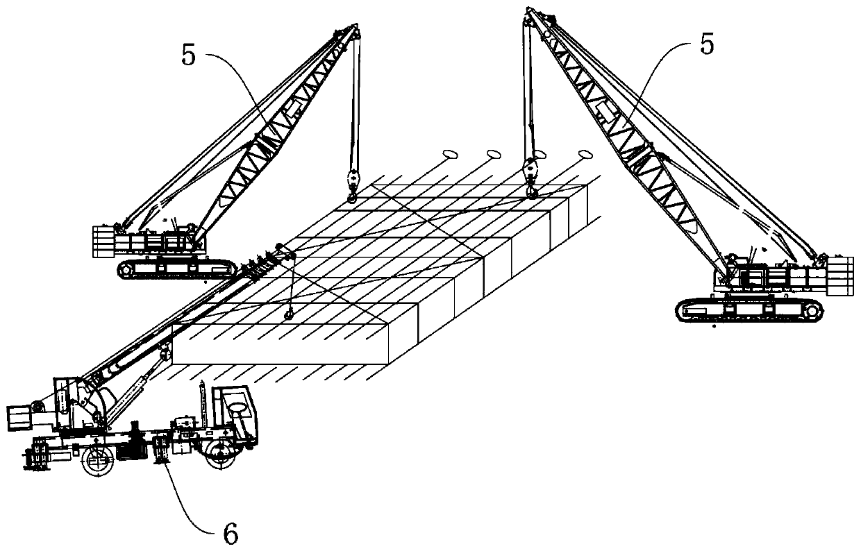
[0059] In the description of the present invention, it should be noted that the terms "center", "upper", "lower", "left", "right", "vertical", "horizontal", "inner", "outer" etc. The indicated orientation or positional relationship is based on the orientation or positional relationship shown in the drawings, and is only for the convenience of describing the present invention and simplifying the description, rather than indicating or implying that the referred device or element must have a specific orientation, o...


PUM

PropertyMeasurementUnit
Widthaaaaaaaaaa

Abstract

The invention provides an underground continuous wall reinforcement cage hoisting method in a height-limited area, and belongs to the field of underground continuous wall construction. The undergroundcontinuous wall reinforcement cage hoisting method comprises a construction preparing process, a hoisting process, a synchronous proceeding and reinforcement cage dropping process and a reinforcementcage orifice welding process, wherein the hoisting process comprises the following steps: S31 of synchronously hoisting three hoists until the reinforcement cage is horizontally hoisted by 1.5-2.0 m,continuously and synchronously hoisting two primary hoists, and dropping a hanger by a secondary hoist; and S32 of completely straightening the reinforcement cage and relieving the hanger of the secondary hoist after weight of the reinforcement cage is borne by the two primary hoists. The underground continuous wall reinforcement cage hoisting method solves the problems that an existing hoistingway has many hoisting times, has many welding and connecting times, consumes time and labor, increases cost, is poor in reinforcement integrity, avoids phenomena such as slot wall hole collapse, cagebody mud entrainment and excessive sediments if time of mounting the reinforcement cage is too long, and slot wall exposure time is too long, and solves the problem that control on underground continuous wall construction quality is bad.

Description

technical field [0001] The invention relates to the construction field of an underground diaphragm wall, in particular to a method for hoisting a reinforcement cage of an underground diaphragm wall in a height-limited area. Background technique [0002] Such as figure 1 As shown, in the construction process of the underground diaphragm wall, under normal circumstances, the reinforcement cage of the wall is integrally manufactured and hoisted into the groove at one time, and the reinforcement cage is hoisted using hooks, shoulder poles, wire ropes and other spreaders 3, usually with a height of about 3.5m . [0003] However, when the construction site is affected by the high-voltage line 1 and is in the height-limited area 2, and the hoisting height on the site is insufficient, the reinforcement cage 4 is made in sections, and the segmented reinforcement cage 4 is connected by welding during hoisting to ensure continuous The integrity of the wall reinforcement. [0004] Th...

Claims


Application Information

Patent Timeline
IPC IPC(8): E02D5/20B66C23/36B66C23/62
CPCB66C23/36B66C23/62E02D5/20
Inventor 高子建雷斌胡静李波李洪勋吴涵申小平许国兵
Owner SHENZHEN GONGKAN GEOTECHN GRP
Features
  • Generate Ideas
  • Intellectual Property
  • Life Sciences
  • Materials
  • Tech Scout
  • Unparalleled Data Quality
  • Higher Quality Content
  • 60% Fewer Hallucinations
Learn More