Offshore wind power suction pile foundation

An offshore wind power and suction pile technology, applied in wind power generation, infrastructure engineering, installation/support of wind turbine configuration, etc., can solve problems such as large bending moment, suction pile soil failure, etc. Overturning moment, cost reduction effect

Pending Publication Date: 2020-07-14
FUJIAN YONGFU POWER ENG
View PDF0 Cites 3 Cited by
  • Summary
  • Abstract
  • Description
  • Claims
  • Application Information

AI Technical Summary

Problems solved by technology

[0005] The technical problem to be solved by the present invention is: how to avoid the large bending moment generated at the rotation center of the suction pile due to the load on the suction pile, resulting in the risk of failure of the soil around the suction pile

Method used


Image

  • Offshore wind power suction pile foundation
  • Offshore wind power suction pile foundation
  • Offshore wind power suction pile foundation

Examples


Embodiment 1

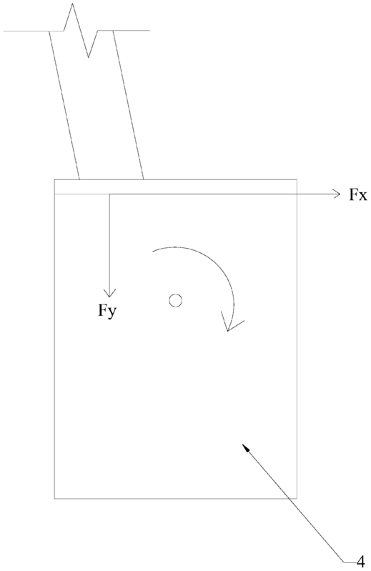
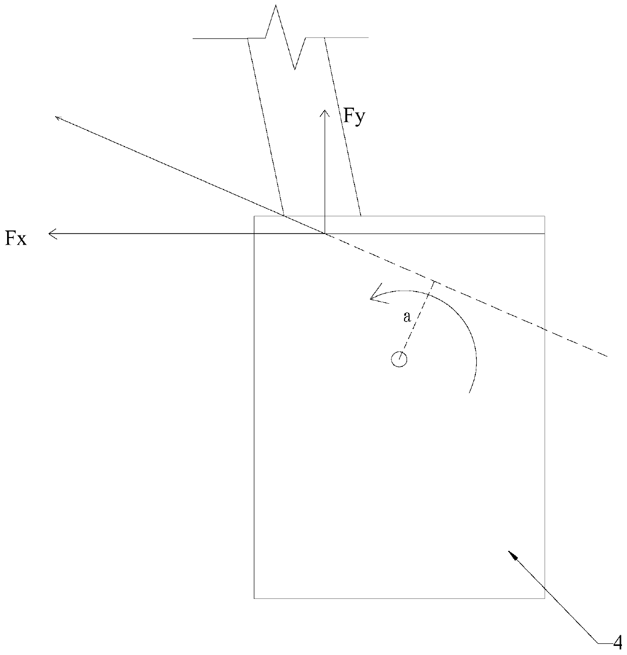
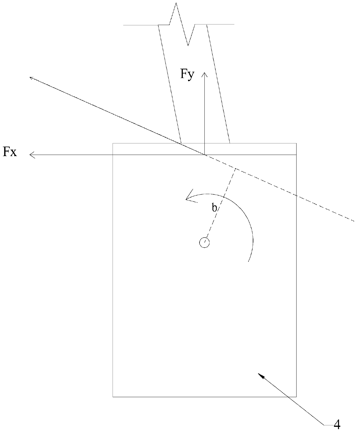
[0042] An offshore wind power suction pile foundation, comprising a wind turbine tower 1, a tower frame 2, a suction pile connection section 3 and a suction pile body 4; the wind turbine tower 1 is vertically connected to the center of the upper part of the tower frame 2, the The lower end of the tower frame 2 is provided with more than three connecting columns 5, the number of the suction pile body 4 is the same as the number of connecting columns 5, and the lower end of each connecting column 5 is respectively connected to the The upper part of the suction pile body 4, the shortest distance between the lower end of each connecting column 5 and the axis of the fan tower 1 is the same; the shape of the suction pile body 4 is a hollow cylinder with an open lower part and a closed upper part, and the connecting column The vertical extension line of the lower end of 5 is located inside the axis of the correspondingly connected suction pile body 4. The axes in turn lie in the same...

Embodiment 2

[0044] An offshore wind power suction pile foundation is characterized in that it includes a wind turbine tower 1, a tower 2, a suction pile connection section 3 and a suction pile body 4; the wind turbine tower 1 is vertically connected to the top of the tower 2 At the center, the lower end of the tower 2 is provided with more than three connecting columns 5, the number of the suction pile body 4 is the same as that of the connecting columns 5, and the lower end of each connecting column 5 passes through the connecting section of the suction pile respectively. 3 are respectively connected to the upper part of the suction pile body 4, and the shortest distance between the lower end of each connecting column 5 and the axis of the wind tower 1 is the same; the shape of the suction pile body 4 is a hollow cylinder with an open lower part and a closed upper part, The vertical extension line of the lower end of the connecting column 5 is located inside the axis of the correspondingl...


PUM


Abstract

The invention relates to the technical field of offshore wind power facility structures, and in particular to an offshore wind power suction pile foundation. The offshore wind power suction pile foundation comprises a fan tower, a tower frame, suction pile connection sections and suction pile bodies; lower ends of connection columns skew inwards to reduce a force arm of a resultant force of wave and current loads on the suction pile bodies, and accordingly, the overturning moment of the wave and current loads on the suction pile bodies is reduced under the condition of the wave and current loads are unchanged in comparison with the prior art, and the problem that soil bodies around the suction pile bodies fail due to the fact that the wave and current loads are excessively large in a traditional technology is solved, and accordingly, the weight of the tower frame can be appropriately reduced, that is, the steel consumption of the tower frame is reduced, and the cost is reduced.

Description

technical field [0001] The invention relates to the technical field of offshore wind power facility structures, in particular to an offshore wind power suction pile foundation. Background technique [0002] At present, offshore wind power has become a research hotspot in the development of global wind power. All countries in the world regard offshore wind power as an important direction for the development of renewable energy, and my country has also listed it as an important part of strategic emerging. [0003] my country is rich in offshore wind energy resources, and the development and construction of wind farms is developing rapidly. Various forms of foundations for offshore wind turbines, such as gravity foundations, single pile foundations, multi-column foundations, and suction foundations, have been applied. Because the suction foundation can be applied to the area where the bedrock of the seabed is buried shallowly and the traditional wind power pile foundation needs...

Claims


Application Information

Patent Timeline
IPC IPC(8): F03D13/25E02D27/42E02D27/24E02D27/52
CPCE02D27/24E02D27/425E02D27/52F03D13/22F03D13/25Y02E10/72Y02E10/727
Inventor 张植宣宋启明游先辉欧寅华吴昀范夏玲熊文亮刘蔚赖福梁
Owner FUJIAN YONGFU POWER ENG
Why Eureka
Try Eureka