
Piezoelectric micromirror structure and preparation method

An electric micromirror and micromirror technology, applied in the field of micromirrors, can solve the problems of difficult control of deflection angle accuracy, complex device sealing, small moving range, etc., and achieve the effects of high deflection angle, simple processing, and improved sealing effect.

Pending Publication Date: 2020-07-14
HANKING ELECTRONICS LIAONING
View PDF5 Cites 1 Cited by
  • Summary
  • Abstract
  • Description
  • Claims
  • Application Information

AI Technical Summary

Problems solved by technology

[0002] The piezoelectric micromirror utilizes the principle that the piezoelectric material expands due to the change of the electric field, so that the micromirror can move within a certain range. The current piezoelectric micromirror has defects such as a small moving range and a large voltage requirement. At the same time, the sealing of the device is complicated, and the deflection angle accuracy Difficult to control

Method used


Image

  • Piezoelectric micromirror structure and preparation method
  • Piezoelectric micromirror structure and preparation method

Examples


Embodiment 1

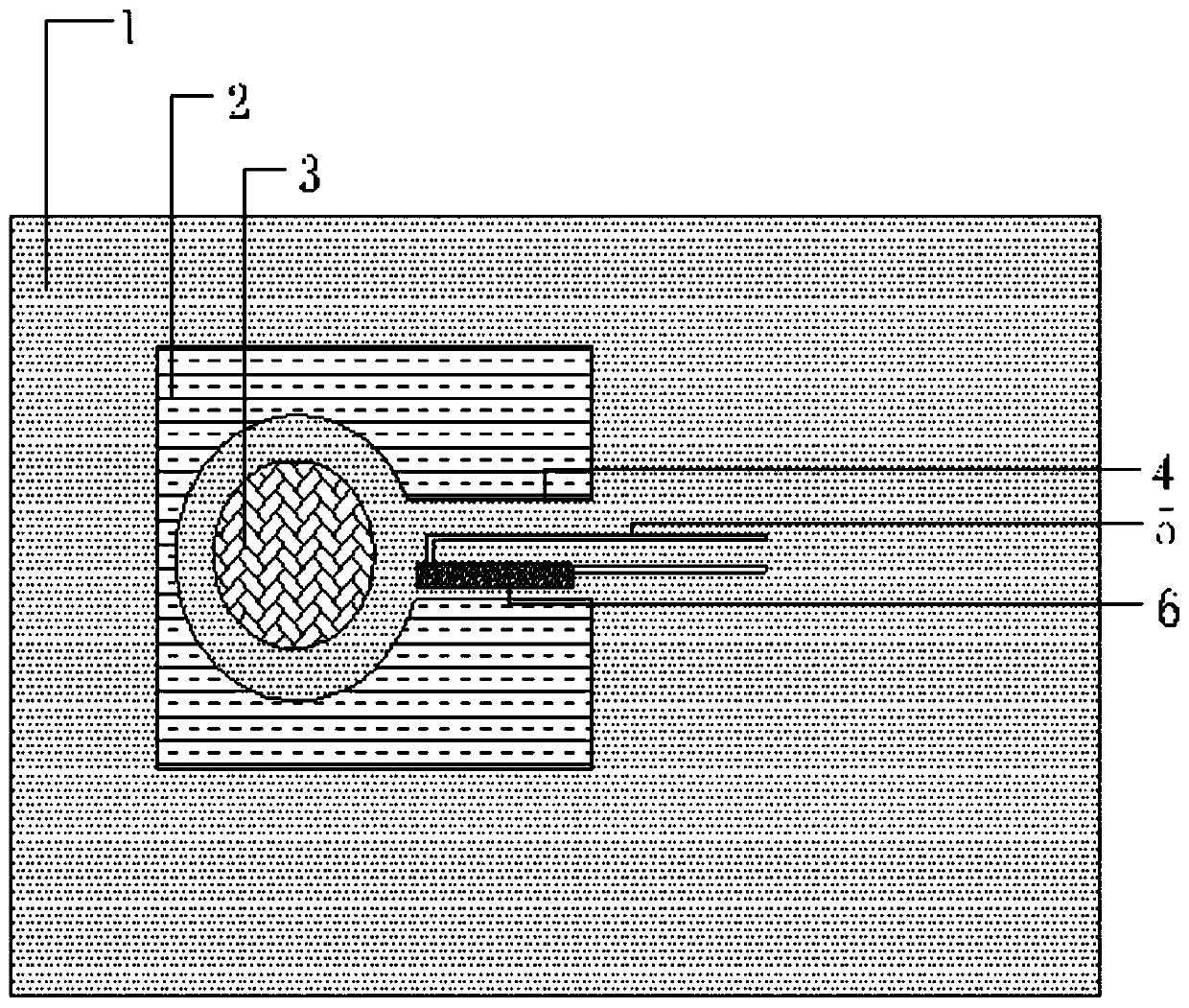
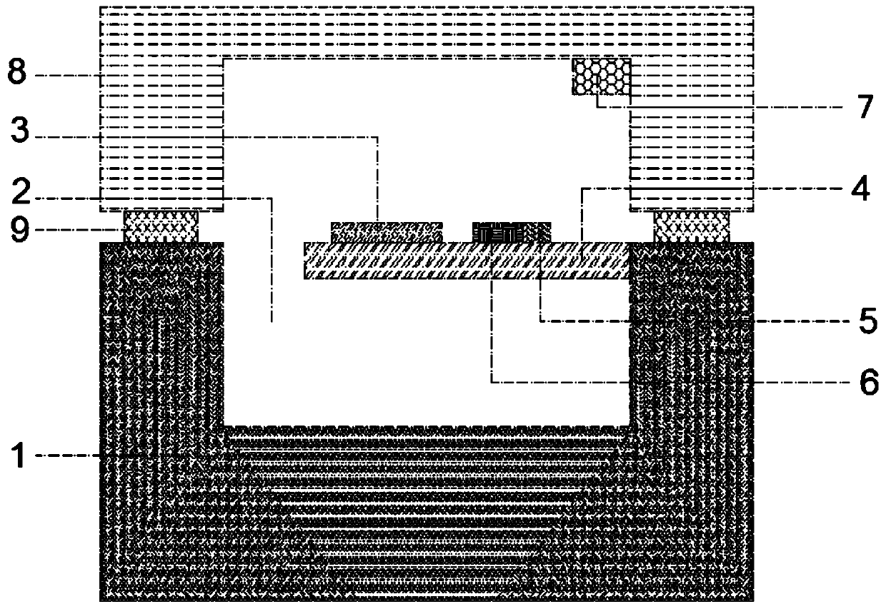
[0019] The present invention provides a piezoelectric micromirror structure, which is characterized in that: the piezoelectric micromirror structure includes a substrate wafer 1, a cavity 2, a mirror metal surface 3, a cantilever beam structure 4, a metal Connecting wire 5, piezoelectric film 6, cover wafer 8, bonding interface 9, getter box 7;

[0020] Among them: the substrate wafer 1 is used as the support and structure layer of the micromirror, the cavity 2 is on the deposition wafer 1, which is a groove structure, and the cavity 2 is formed after the wafer is bonded; the metal surface 3 of the mirror is arranged on the The surface of the micromirror is made of a metal mirror surface, and the micromirror is connected to the substrate wafer 1 through one or more cantilever beam structures 4; The thin film 6 is connected to the metal connection 5. When the electricity is applied, the piezoelectric thin film will generate a force, causing the cantilever beam to bend, and the ...

Embodiment 2

[0028] The present invention provides a piezoelectric micromirror structure, which is characterized in that: the piezoelectric micromirror structure includes a substrate wafer 1, a cavity 2, a mirror metal surface 3, a cantilever beam structure 4, a metal Connecting wire 5, piezoelectric film 6, cover wafer 8, bonding interface 9, getter box 7;

[0029] Among them: the substrate wafer 1 is used as the support and structure layer of the micromirror, the cavity 2 is on the deposition wafer 1, which is a groove structure, and the cavity 2 is formed after the wafer is bonded; the metal surface 3 of the mirror is arranged on the The surface of the micromirror is made of a metal mirror surface, and the micromirror is connected to the substrate wafer 1 through one or more cantilever beam structures 4; The thin film 6 is connected to the metal connection 5. When the electricity is applied, the piezoelectric thin film will generate a force, causing the cantilever beam to bend, and the ...

Embodiment 3

[0037]The present invention provides a piezoelectric micromirror structure, which is characterized in that: the piezoelectric micromirror structure includes a substrate wafer 1, a cavity 2, a mirror metal surface 3, a cantilever beam structure 4, a metal Connecting wire 5, piezoelectric film 6, cover wafer 8, bonding interface 9, getter box 7;

[0038] Among them: the substrate wafer 1 is used as the support and structure layer of the micromirror, the cavity 2 is on the deposition wafer 1, which is a groove structure, and the cavity 2 is formed after the wafer is bonded; the metal surface 3 of the mirror is arranged on the The surface of the micromirror is made of a metal mirror surface, and the micromirror is connected to the substrate wafer 1 through one or more cantilever beam structures 4; The thin film 6 is connected to the metal connection 5. When the electricity is applied, the piezoelectric thin film will generate a force, causing the cantilever beam to bend, and the m...


PUM


Abstract

A piezoelectric micromirror structure comprises a substrate wafer, a reflector metal surface, a cantilever beam structure, a metal connecting wire, a piezoelectric film, a cover plate wafer, a bondinginterface and a getter box, wherein the substrate wafer is used as a supporting and structural layer of the micromirror, the metal connecting wire is a film-shaped connecting wire, and the piezoelectric film is arranged on the cantilever beam structure. According to the preparation method for the piezoelectric micromirror structure, the substrate wafer is used as a supporting and structural layerof the micromirror, and a cavity is formed after wafer bonding; a metal reflecting mirror surface of the micromirror is manufactured by utilizing a physical vapor deposition plan, a photoetching technology, an etching or stripping technology and a polishing technology; the piezoelectric film is prepared on the cantilever beam by using a physical vapor deposition or chemical vapor deposition technology, the photoetching technology and the etching technology. The structure has the advantages that the processing is simple, the cantilever beam structure is adopted, the piezoelectric material is deposited on the cantilever beam structure, the metal surface is used as a reflector, one or more groups of arranged mirror surfaces can be packaged, the function of an optical switch and a higher deflection angle are realized, and the displacement control is accurate.

Description

technical field [0001] The invention relates to the field of micromirrors, in particular to a structure and a preparation method of a piezoelectric micromirror. Background technique [0002] The piezoelectric micromirror utilizes the principle that the piezoelectric material expands due to the change of the electric field, so that the micromirror can move within a certain range. The current piezoelectric micromirror has defects such as a small moving range and a large voltage requirement. At the same time, the sealing of the device is complicated, and the deflection angle accuracy Difficult to control. Contents of the invention [0003] The object of the present invention is to overcome the above-mentioned problems, and especially provide a structure and a preparation method of a piezoelectric micromirror. [0004] The present invention provides a piezoelectric micromirror structure, which is characterized in that: the piezoelectric micromirror structure includes a substr...

Claims


Application Information

Patent Timeline
Patent Type & Authority Applications(China)
IPC IPC(8): G02B26/08
CPCG02B26/0858
Inventor 黄向向杨敏道格拉斯·雷·斯巴克斯关健孙斯佳
Owner HANKING ELECTRONICS LIAONING
Learn More