Multi-functional fully automatic hydraulic pressure bander
A fully automatic and multi-functional technology, applied in the field of agricultural machinery, can solve problems such as poor working environment, low efficiency, and low degree of automation
- Summary
- Abstract
- Description
- Claims
- Application Information
AI Technical Summary
Problems solved by technology
Method used
Image
Examples
Embodiment 1
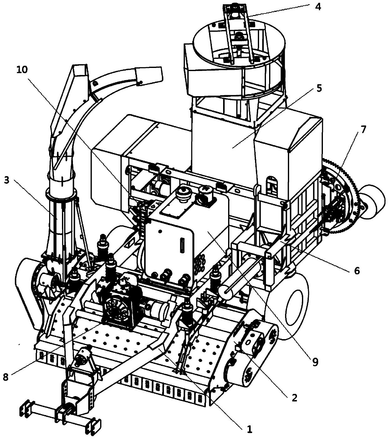
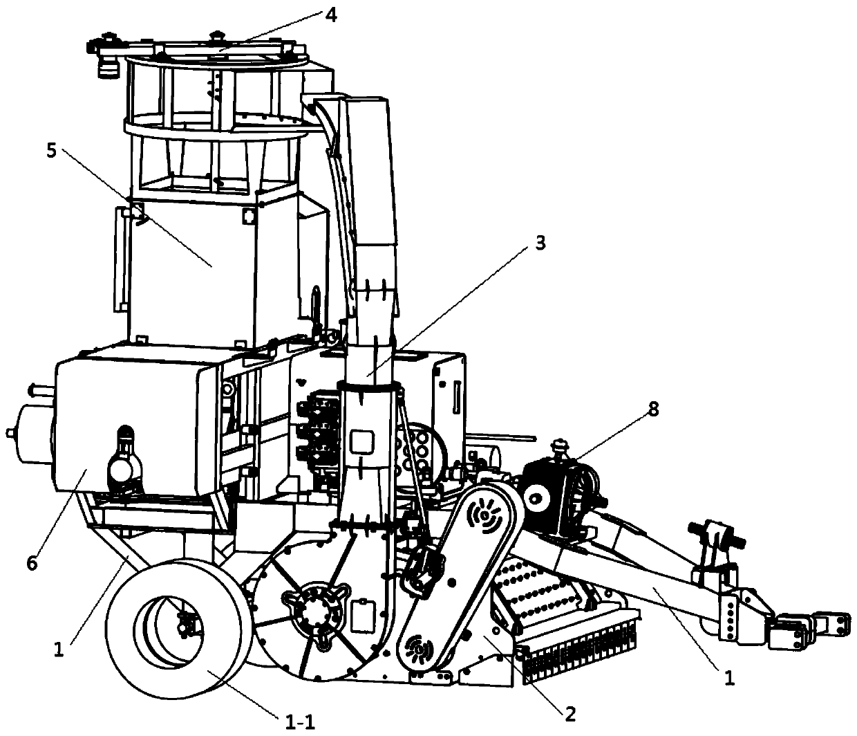
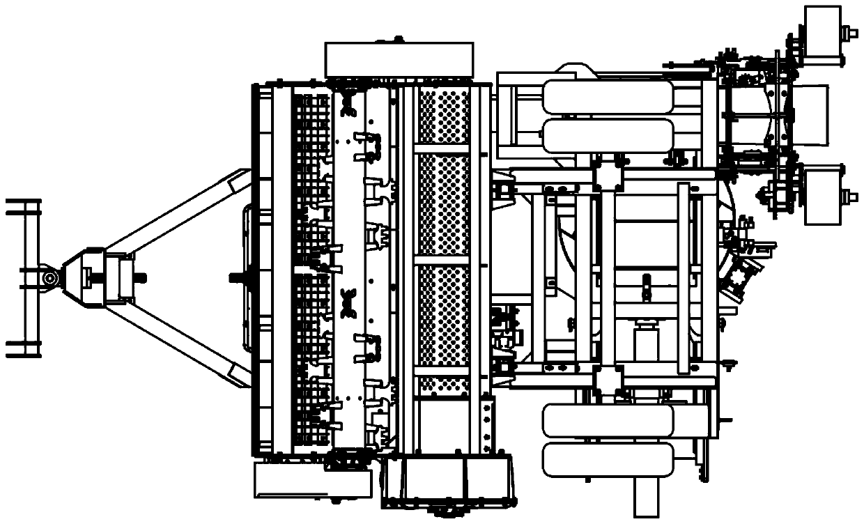
[0068] In this embodiment, a multifunctional fully automatic hydraulic strapping machine consists of a main frame 1, a picker 2, a conveying air cylinder 3, a collection bin 5, a hydraulic bundling device 6, an automatic net wrapping device 7, a gearbox 8 and Composition of hydraulic oil tank 9;
[0069] The gearbox 8 is arranged at the front end of the main frame 1, and the picker 2 is fixedly installed under the main frame 1, and is connected to the output shaft of the gearbox 8. The hydraulic oil tank 9 is installed in the middle of the main frame 1, and the hydraulic oil is installed at the rear of the main frame 1. The bundling device 6, the collection bin 5 is set above the hydraulic bundling device 6; the walking wheel 1-1 is provided under the rear of the main frame 1; the picker 2 is integrated with a fan, and the conveying air cylinder 3 is installed Above the fan, the outlet is connected to the collection bin 5;
[0070] The hydraulic baling device 6 is mainly composed ...
Embodiment 2
[0096] The multifunctional fully automatic hydraulic baler described in this embodiment also includes an automatic weeding device 4, which consists of a bracket 4-1, a hydraulic motor I 4-2, a bearing 4-3, and a rotating rod 4. -4, composed of 4-5 straws.
[0097] Among them, the bracket 4-1 is a rectangular frame structure and is fixed on the top of the collection bin; the bearing 4-3 is fixed in the middle of the bracket 4-1 through the bearing seat; the rotating rod 4-4 extends from the opening in the top center of the collection bin In the collection bin, the top end is connected with the central shaft in the bearing 4-3. The middle and lower parts of the rotating rod 4-4 are equipped with several grass rods 4-5; the central shaft in the bearing 4-3 is connected to a driven wheel The end of the bracket 4-1 is located outside the collecting bin and is fixedly installed with a hydraulic motor I4-2; the output shaft of the hydraulic motor I4-2 is connected to a driving wheel, an...
Embodiment 3
[0102] The multifunctional fully automatic hydraulic strapping machine described in this embodiment also includes a mechanical fuel tank heat dissipation mechanism, which includes an active pulley 9-1 installed at the left end of the central shaft 8-4 of the gearbox 8 and installed in the hydraulic oil tank 9 The fan 9-2 at the radiating hole, the fan 9-2 is connected with the driven pulley 9-3, the driving pulley 9-1 and the driven pulley 9-3 are provided with a double belt pulley 9-4; a double belt pulley 9 -4 is formed by connecting a large pulley and a small pulley, the small pulley and the driving pulley 9-1 are driven by a belt, and the large pulley and the driven pulley 9-3 are driven by a belt.
PUM
 Abstract
Description
Claims
Application Information
 - R&D
- Intellectual Property
- Life Sciences
- Materials
- Tech Scout
- Unparalleled Data Quality
- Higher Quality Content
- 60% Fewer Hallucinations
Browse by: Latest US Patents, China's latest patents, Technical Efficacy Thesaurus, Application Domain, Technology Topic, Popular Technical Reports.
© 2025 PatSnap. All rights reserved.Legal|Privacy policy|Modern Slavery Act Transparency Statement|Sitemap|About US| Contact US: help@patsnap.com


