A Metal Surface Grinding System Based on Industrial Vision
A metal surface and visual technology, applied in metal processing equipment, workpiece feed motion control, grinding machines, etc., can solve the problem of repetitive and heavy manual grinding of metal surfaces, to ensure the uniformity and surface quality of grinding, and avoid repairing. Grinding waste and improving grinding efficiency
- Summary
- Abstract
- Description
- Claims
- Application Information
AI Technical Summary
Problems solved by technology
Method used
Image
Examples
example 1
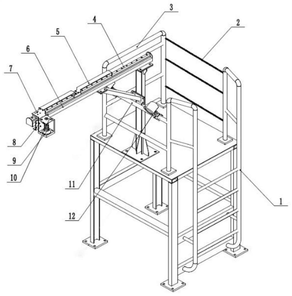
[0043] A six-axis robot arm grinding system based on industrial vision metal surface, the frame structure of the vision acquisition device is as follows: image 3 As shown, the grinding robot is as Figure 4 shown.
[0044] Climbing ladder 1 is convenient for technicians to climb heights and adjust the position of the camera; fence 2 and replacement handrail 3 ensure the safety of technicians working on the platform; slide rail A4 and slide rail B 5 are convenient for installing and adjusting the camera position; slide rail brackets 6 pairs of sliding The rail A4 and the slide rail B5 play a supporting role; the camera 9 is used to collect the surface image of the steel plate; the camera bracket 7 and the camera housing 8 support and protect the camera 9; the cooling device 10 is used to dissipate heat for the camera 9; The camera collects the brightness of the field of view to reduce the interference of ambient light; the beam 11 of the light frame supports the cooling devic...
example 2
[0051] A metal surface gantry robot arm grinding system based on industrial vision, the layout is as follows Figure 6 shown. The support column 13 supports the Y-axis main beam 16; the grinding arm 14 is used for grinding defects; the beam 15 is used for the grinding arm 14 to move along the X direction; the Y-axis main beam 16 is used for the beam 15 to move along the Y direction; The industrial camera 17 is used to collect the surface image of the steel plate; the auxiliary light source support frame 18 is used to place the auxiliary light source.
[0052] Fixed columns are placed on both sides of the roller table, and the Y-axis main beam 16 is placed on the top. The beam is placed between the two Y-axis main beams and can move in the Y direction. The robot arm is suspended under the beam. Cameras are placed on both sides of the Y-axis main beam and tilted at 45° The steel plate is photographed, and a strip LED light source is placed below for supplementary light.
[005...
PUM
 Abstract
Description
Claims
Application Information
 - R&D
- Intellectual Property
- Life Sciences
- Materials
- Tech Scout
- Unparalleled Data Quality
- Higher Quality Content
- 60% Fewer Hallucinations
Browse by: Latest US Patents, China's latest patents, Technical Efficacy Thesaurus, Application Domain, Technology Topic, Popular Technical Reports.
© 2025 PatSnap. All rights reserved.Legal|Privacy policy|Modern Slavery Act Transparency Statement|Sitemap|About US| Contact US: help@patsnap.com


