
Metal surface grinding system based on industrial vision

A metal surface and visual technology, which is used in metal processing equipment, workpiece feed motion control, grinding machines, etc., can solve the problems of repetitive and heavy manual grinding of metal surfaces, achieve precise and controllable grinding amount, and avoid grinding waste. , The effect of reducing grinding waste

Active Publication Date: 2020-07-17
NORTHEASTERN UNIV
View PDF8 Cites 15 Cited by
  • Summary
  • Abstract
  • Description
  • Claims
  • Application Information

AI Technical Summary

Problems solved by technology

[0004] The purpose of the present invention is to solve many problems caused by repeated and heavy manual grinding of metal surfaces, and realize the intelligent control of active identification and automatic grinding

Method used


Image

  • Metal surface grinding system based on industrial vision
  • Metal surface grinding system based on industrial vision
  • Metal surface grinding system based on industrial vision

Examples


example 1

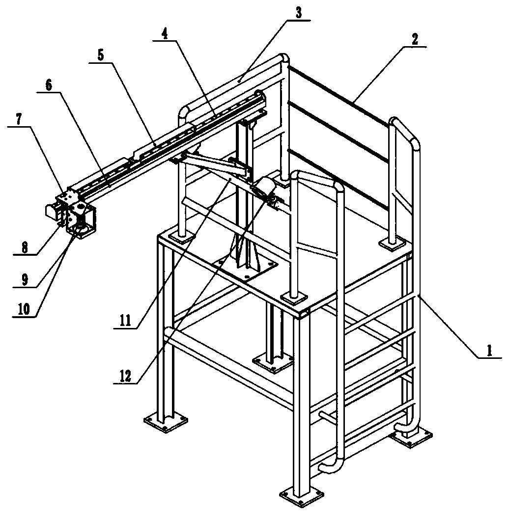
[0043] A six-axis robot arm grinding system based on industrial vision metal surface, the frame structure of the vision acquisition device is as follows: image 3 As shown, the grinding robot is as Figure 4 shown.

[0044] Climbing ladder 1 is convenient for technicians to climb heights and adjust the position of the camera; fence 2 and replacement handrail 3 ensure the safety of technicians working on the platform; slide rail A4 and slide rail B 5 are convenient for installing and adjusting the camera position; slide rail brackets 6 pairs of sliding The rail A4 and the slide rail B5 play a supporting role; the camera 9 is used to collect the surface image of the steel plate; the camera bracket 7 and the camera housing 8 support and protect the camera 9; the cooling device 10 is used to dissipate heat for the camera 9; The camera collects the brightness of the field of view to reduce the interference of ambient light; the beam 11 of the light frame supports the cooling devic...

example 2

[0051] A metal surface gantry robot arm grinding system based on industrial vision, the layout is as follows Image 6 shown. The support column 13 supports the Y-axis main beam 16; the grinding arm 14 is used for grinding defects; the beam 15 is used for the grinding arm 14 to move along the X direction; the Y-axis main beam 16 is used for the beam 15 to move along the Y direction; The industrial camera 17 is used to collect the surface image of the steel plate; the auxiliary light source support frame 18 is used to place the auxiliary light source.

[0052] Fixed columns are placed on both sides of the roller table, and the Y-axis main beam 16 is placed on the top. The beam is placed between the two Y-axis main beams and can move in the Y direction. The robot arm is suspended under the beam. Cameras are placed on both sides of the Y-axis main beam and tilted at 45° The steel plate is photographed, and a strip LED light source is placed below for supplementary light.

[0053...


PUM


Abstract

The invention belongs to the technical field of metal surface grinding, and discloses a metal surface grinding system based on industrial vision. The metal surface grinding system comprises a visual processing system, a grinding movement system and an auxiliary system, wherein the grinding movement system is combined with the visual processing system to finely divide a to-be-ground area, excessivegrinding waste is avoided, and the grinding efficiency is improved; a force balance device is combined with depth detection, the grinding force and the reasonable downward pressing amount are controlled in real time, and the grinding uniformity and the surface quality are guaranteed; and the grinding recognition rate and the grinding quality of the whole system are multiply guaranteed, and grinding personnel in severe environments can be greatly reduced or replaced in practical application.

Description

technical field [0001] The invention relates to the technical field of metal surface grinding, in particular to a metal surface grinding system based on industrial vision. Background technique [0002] Surface finish is one of the important indicators of the product. In the material processing and manufacturing industry, some defects will inevitably appear on the surface of metal products during the production process, such as scratches, cracks, pits and inclusions, etc., which seriously affect the product surface quality and subsequent use or reprocessing. With the development of social economy, the market has put forward higher and higher requirements for product quality, so the requirements for product surface treatment are becoming increasingly strict. Taking steel mills as an example, mechanical grinding is generally used to repair and polish the surface of steel products. At present, almost all steel mills in my country adopt the traditional manual grinding method. T...

Claims


Application Information

Patent Timeline
Patent Type & Authority Applications(China)
IPC IPC(8): B24B19/00B24B49/12B24B41/00B24B51/00B24B55/06B24B55/12B25J11/00G06T7/00G06T5/00G06T7/62G06T7/90G06K9/32
CPCB24B19/00B24B49/12B24B41/007B24B51/00B24B55/06B24B55/12B25J11/0065G06T7/0004G06T7/62G06T7/90G06V10/25G06T5/94
Inventor 张田王昭东田勇王丙兴李家栋
Owner NORTHEASTERN UNIV
Learn More