Contact sliding telescopic fan blade

A fan blade and fan blade technology is applied in the fields of helicopter wind rotor blades and large industrial ceiling fan blades. Clean fan blades, low friction effect

Inactive Publication Date: 2020-07-17
毛永波
View PDF0 Cites 3 Cited by
  • Summary
  • Abstract
  • Description
  • Claims
  • Application Information

AI Technical Summary

Problems solved by technology

[0002] The invisible fan can be more conveniently stored automatically when idle, further simplifying and beautifying the home environment, and becoming a simple furniture appliance. The current radially telescopic invisible fan is a multi-section movable connecting fan blade with a first-level locking buckle. The overlapping buckle connection, the fan generates strong centrifugal force during high-speed operation, causing the fan blades to be more or less distorted and deformed, and there is a great risk of tripping. Once the tripping scatteres and forms a high-speed dart, it will cause a great safety accident. Preventing and ensuring retractable fan blade tripping and flying is a key safety issue
[0003] The current large-scale fans are all fixed, and the large-scale fans are relatively heavy, and the installation height is particularly high. Professional equipment is required for installation, disassembly and maintenance. When the weather is cool and the fan is idle, the large-scale fan seems to be in the way, especially the dust in the air of the factory. Many, long-term operation of the fan blades accelerate the adhesion of thick air dust, which is particularly inelegant. A large elevator must be erected to clean it manually, and the blades of the large fan are long, and the large elevator must also move far along the ground horizontally It takes only a distance to clean a fan blade, which is difficult, time-consuming and laborious
[0004] Although the existing invisible fans with swinging blades and discs can hide the fan blades, the shrunken fan blades can still be seen, especially after a long period of operation, the fan blades become black after absorbing air dust. Even if the fan blades are shrinking, the black dust adhering to the shrinking fan blades can still be clearly seen, which must be cleaned manually on a regular basis; and the expansion range of the fan blades is small, it is impossible to manufacture industrial-grade large fans, and the slightly expanded range of the fan blades must increase the diameter of the lighting. The invisible fan blades can only be achieved by covering up the body, which leads to the lack of flexibility in matching lighting decorations. A lighting decoration with a diameter can only be equipped with a fan with a diameter
[0005] The multi-section linear telescopic fan blades are directly stretched and retracted by the sleeve friction of the large and small sections. Although the fan blades are telescopic and automatically cleaned, there is a large friction surface between each section of the blade, and the friction is large. The stretching action is not smooth, and there is often a non-shrinking or half-shrinking state, and the stretching friction area is too large to produce annoying friction noise
[0006] The retractable invisible fan has the risk of tripping and hinge dart due to the deformation of the fan blade, which poses a safety hazard
[0007] Helicopter wind rotor blades are long and take up a lot of space, making storage difficult. If the blades are unloaded and stored, it is difficult to assemble them in an emergency

Method used


Image

  • Contact sliding telescopic fan blade
  • Contact sliding telescopic fan blade
  • Contact sliding telescopic fan blade

Examples


Embodiment 1

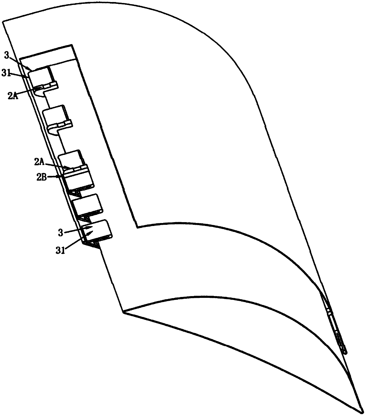
[0111] Embodiment one: if figure 1 , 2 As shown in , 3, 420 grade stainless steel meniscus curved surface straight tube fan blade, plastic slider and V-shaped sliding contact sliding telescopic fan blade, including: multiple contact sliders 2 and at least two-level limit cards Hasp 3; characterized in that: the plurality of contact sliders 2 are set on the surface and slideway of the telescopic fan blade 1 to touch and slide the telescopic fan blade 1; the limit locking hasp 3 is fixedly connected to The inside of one end of the slideway on both sides of each telescopic fan blade and the outside of the other end of the two sides of the slideway are arranged in a linear array at least two, forming at least one level of buckle and two levels of anti-off; the contact slider 2 is fixedly connected Slidingly touch the fan blade on the limit locking buckle 3;

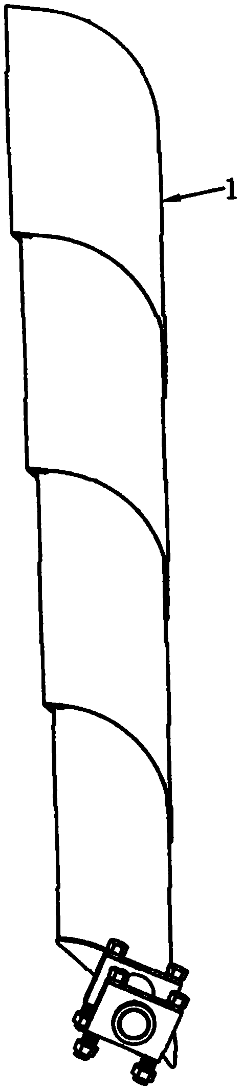
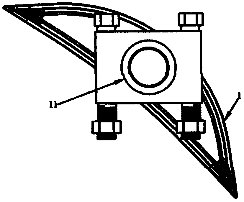
[0112] The telescopic fan blade 1 is composed of multi-section large and small casing coaxially sliding and telescopic so...

Embodiment 2

[0123] Embodiment two: if figure 1 , 2 , 3, 65Mn grade carbon spring steel meniscus curved surface straight tube fan blade, graphite slider and V-shaped slideway contact sliding telescopic fan blade, the structure of the second embodiment is similar to the first embodiment, the difference is:

[0124] The multi-section casing fan blade is formed by bending and forming metal carbon spring steel 65Mn grade sheet metal;

[0125] The contact slider is pure carbon graphite M191T made of graphite; the graphite block made of graphite is fixedly connected to the limit locking buckle 3 to slide the fan blade;

[0126] Lubricating powder is adhered to the surface of the multi-section casing fan blade and the contact slider 2 to reduce friction and noise; the lubricating powder is graphite powder; the graphite powder is ground on the surface of each casing fan blade and the fan blade original groove 37 of the contact slider 2 touches and slides the fan blade;

[0127] The graphite pow...

Embodiment 3

[0129] Embodiment three: as Figure 5 , 9 As shown in . Locking hasp 3; characterized in that: the plurality of contact sliders 2 are set on the surface and slideway of the telescopic fan blade 1 to touch and slide the telescopic fan blade 1; the limit locking hasp 3 is fixedly connected There are at least two linear arrays on the inside of one end of the slideway on both sides of each telescopic fan blade and the outside of the other end of the two sides of the slideway, forming at least one level of buckle and two levels of anti-off; the contact slider 2 is fixed Connected to the limit locking buckle 3 to slide the fan blade;

[0130] The telescopic fan blade 1 is composed of multi-section large and small casing coaxially sliding and telescopic sockets to form a casing fan blade, and a limit locking buckle 3 is respectively set on the inner side of one end of the casing and the outer side of the other end of the casing. ;

[0131] Such as Figure 40 , 43 , as shown, th...


PUM


Abstract

The invention provides a contact sliding telescopic fan blade. The contact sliding telescopic fan blade comprises a plurality of contact sliding blocks and at least two stages of limiting clamping hasps. The contact sliding telescopic fan blade is characterized in that the contact sliding blocks are arranged on the surface of the telescopic fan blade and a sliding way to make contact with the fanblade, wherein the limiting clamping hasps are connected to the inner side of one end of the sliding way of each section of telescopic fan blade and the outer side of the other end of the sliding way,and at least two limiting clamping hasps are arranged in a linear array mode, so that at least one stage of buckle and two stages of disengagement prevention are formed; the cross section of one endof a sleeve fan blade is sealed and plugged, so that the fan blade is prevented from deforming and disengaging; the fan blade is provided with piers or pit grooves or T-shaped ribs, so that friction is reduced, and bending resistance is enhanced; the plastic, rubber or graphite contact sliding blocks and the fan blade are attached with a lubricating agent or graphite powder to make contact with the fan blade in a sliding mode, so that friction is reduced; and the strip-shaped contact sliding blocks protrude outwards or protrude inwards to make contact with the fan blade in a sliding mode, andthe fan blade is cleaned. According to the contact sliding telescopic fan blade, the fan blade is connected with an anti-disengagement safety part, multi-stage buckles are used for disengagement prevention, a safety rope is used for disengagement prevention, a power source is automatically turned off when disengagement is carried out, the telescopic range of the fan blade is enlarged, the diameterof a lamp does not need to be increased, and the lamp can be flexibly matched.

Description

【Technical field】 [0001] The invention relates to a wind rotor blade, in particular to a household ceiling fan blade, a large industrial ceiling fan blade and a helicopter wind rotor blade. 【Background technique】 [0002] The invisible fan can be more conveniently stored automatically when idle, further simplifying and beautifying the home environment, and becoming a simple furniture appliance. The current radially telescopic invisible fan is a multi-section movable connecting fan blade with a first-level locking buckle. The overlapping buckle connection, the fan generates strong centrifugal force during high-speed operation, causing the fan blades to be more or less distorted and deformed, and there is a great risk of tripping. Once the tripping scatteres and forms a high-speed dart, it will cause a great safety accident. Preventing and ensuring that the retractable fan blades are tripped and scattered is a key safety issue. [0003] The current large-scale fans are all fi...

Claims


Application Information

Patent Timeline
Patent Type & Authority Applications(China)
IPC IPC(8): F04D29/38F04D29/34F04D29/02F04D25/08B64C27/473
CPCB64C27/473B64C2027/4733F04D25/088F04D29/023F04D29/34F04D29/384F04D29/388
Inventor 毛永波
Owner 毛永波
Why Eureka
Try Eureka