
LED bracket feeding device and LED solid crystal equipment

A technology for LED brackets and material boxes, which is applied in transportation and packaging, semiconductor/solid-state device manufacturing, semiconductor devices, etc., and can solve the problems of low positioning accuracy and low feeding efficiency of LED brackets

Active Publication Date: 2020-10-27
SHENZHEN XINYICHANG TECH CO LTD
View PDF7 Cites 0 Cited by
  • Summary
  • Abstract
  • Description
  • Claims
  • Application Information

AI Technical Summary

Problems solved by technology

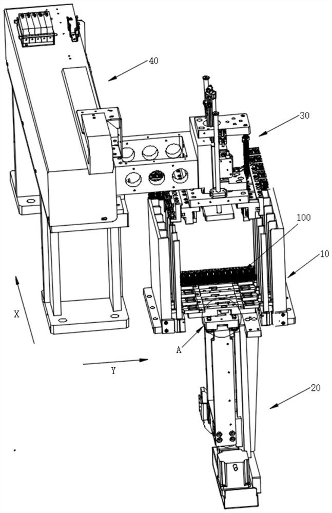
[0003] The purpose of the embodiments of the present application is to provide a LED bracket loading device to solve the technical problems of low LED bracket loading efficiency and low positioning accuracy in the prior art

Method used


Image

  • LED bracket feeding device and LED solid crystal equipment
  • LED bracket feeding device and LED solid crystal equipment
  • LED bracket feeding device and LED solid crystal equipment

Examples


Embodiment Construction

[0028] In order to make the technical problems, technical solutions and beneficial effects to be solved by the present application clearer, the present application will be further described in detail below in conjunction with the accompanying drawings and embodiments. It should be understood that the specific embodiments described here are only used to explain the present application, and are not intended to limit the present application.

[0029] It should be noted that when an element is referred to as being “fixed” or “disposed on” another element, it may be directly on the other element or be indirectly on the other element. When an element is referred to as being "connected to" another element, it can be directly connected to the other element or indirectly connected to the other element.

[0030] It is to be understood that the terms "length", "width", "top", "bottom", "front", "rear", "left", "right", "vertical", "horizontal", "top" , "bottom", "inner", "outer" and oth...


PUM


Abstract

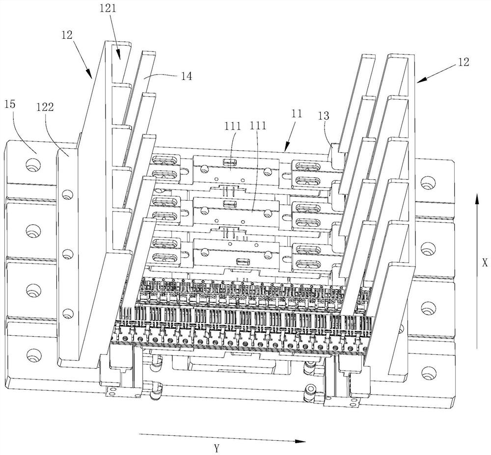
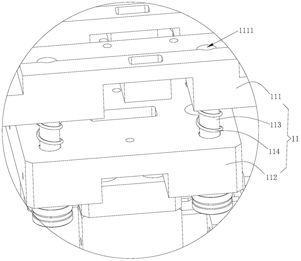
The invention provides an LED support feeding device which comprises a feeding box, a lifting mechanism, a gripper mechanism and a driving mechanism. The feeding box comprises a supporting plate assembly, and a plurality of piles of LED supports can be placed on the supporting plate assembly. The lifting mechanism is used for driving the supporting plate assembly and multiple piles of LED supportsto ascend and descend so that all the LED supports located on the topmost layer can be located on the to-be-grabbed station. The driving mechanism is used for driving the gripper mechanism to move tothe position above multiple piles of LED supports, and the gripper mechanism is used for gripping and transferring the LED supports located on the to-be-gripped station; the gripper mechanism comprises a pre-pressing assembly, a limiting assembly and a gripper assembly, the pre-pressing assembly is used for pressing all the LED supports in advance, the limiting assembly is used for limiting all the LED supports in the horizontal direction, and the gripper assembly is used for gripping all the LED supports. The invention also provides LED die bonding equipment which comprises the LED support feeding device. According to the LED support feeding device, the feeding efficiency of the LED support is improved.

Description

technical field [0001] The present application belongs to the field of LED crystal bonding technology, and more specifically relates to an LED bracket loading device and LED crystal bonding equipment. Background technique [0002] LED crystal bonding machine is a professional equipment for bonding LED products. The traditional LED die bonding machine generally uses a suction cup structure to absorb and place the LED brackets one by one on the working platform, and then carry out the die bonding. However, this feeding method not only has low efficiency and low positioning accuracy, but also cannot be sucked again after the LED bracket is glued, which is inconvenient to operate. Contents of the invention [0003] The purpose of the embodiments of the present application is to provide a LED bracket loading device to solve the technical problems of low LED bracket loading efficiency and low positioning accuracy existing in the prior art. [0004] In order to achieve the abov...

Claims


Application Information

Patent Timeline
Patent Type & Authority Patents(China)
IPC IPC(8): H01L21/677H01L21/68H01L21/687H01L33/48
CPCH01L21/67742H01L21/68H01L21/68742H01L33/48H01L2933/0033
Inventor 胡新荣
Owner SHENZHEN XINYICHANG TECH CO LTD
Learn More