Short-wave double-layer log-periodic antenna fan-shaped array with rigid structure

A log-periodic antenna and rigid structure technology, applied in log-periodic antennas, antenna arrays, radiating element structures, etc., can solve the problems of signal phase noise degradation, difficulty in on-site maintenance, and imperfection of several-period antennas. Directivity gain, high gain, the effect of ensuring wideband characteristics

Active Publication Date: 2020-07-17
泰兴英武舟科技有限公司
View PDF8 Cites 5 Cited by
  • Summary
  • Abstract
  • Description
  • Claims
  • Application Information

AI Technical Summary

Problems solved by technology

[0002] At present, the antenna curtain of the existing short-wave logarithmic period antenna generally adopts a flexible vibrator and suspension cable structure, and the support tower usually adopts a cable tower. The antenna curtain needs to be lowered to the ground during antenna maintenance and inspection, which makes on-site maintenance difficult.
[0003] In addition, when the flexible structure logarithmic periodic antenna is used as a radar antenna, due to the influence of the wind, the flexible vibrator, suspension cable and supporting tower wire will have a large shake, which will cause the phase modulation of the transmitted / received signal and degrade the phase noise of the signal. Thus affecting the detection performance of the radar system for low-speed targets
So the existing shortwave logarithmic periodic antenna is not perfect enough

Method used


Image

  • Short-wave double-layer log-periodic antenna fan-shaped array with rigid structure
  • Short-wave double-layer log-periodic antenna fan-shaped array with rigid structure
  • Short-wave double-layer log-periodic antenna fan-shaped array with rigid structure

Examples


Embodiment Construction

[0032] In order to make the object, technical solution and advantages of the present invention clearer, the present invention will be further described in detail below in conjunction with the accompanying drawings and embodiments. It should be understood that the specific embodiments described here are only used to explain the present invention, not to limit the present invention. In addition, the technical features involved in the various embodiments of the present invention described below can be combined with each other as long as they do not constitute a conflict with each other. The present invention will be further described in detail below in combination with specific embodiments.

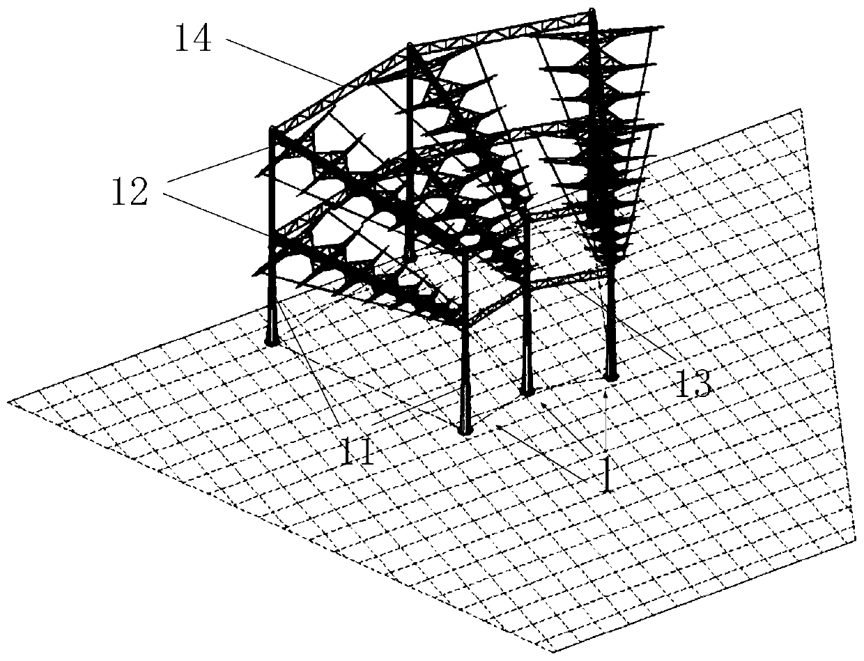
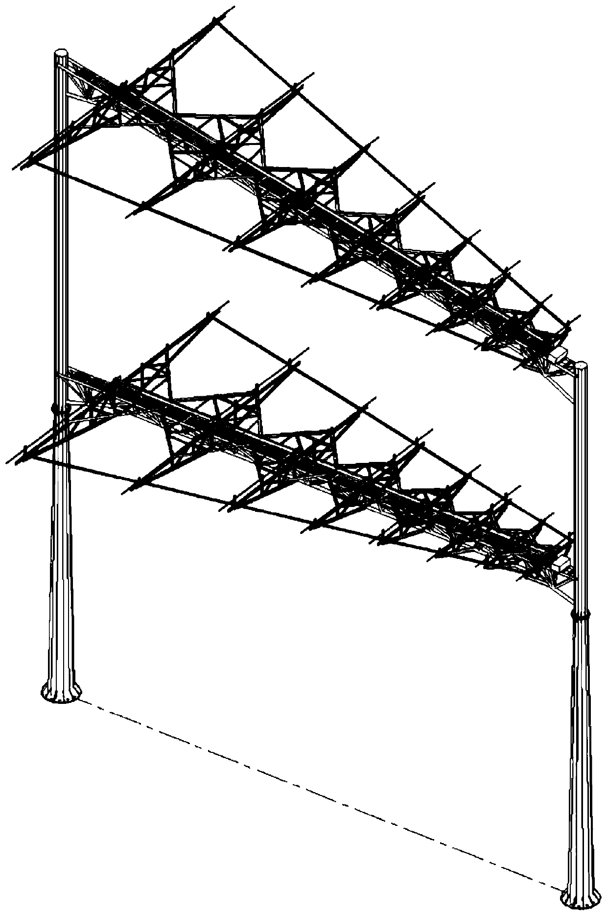
[0033] As a preferred embodiment of the present invention, the present invention provides a 3 × 2 logarithmic periodic antenna sector array based on double-layer door-shaped brackets (also can be composed of 2 × 2 unit horizontal logarithmic periodic antenna sector arrays, that is, 2 groups ...


PUM


Abstract

The invention discloses a short-wave double-layer logarithm periodic antenna fan-shaped array with a rigid structure. The short-wave double-layer logarithm periodic antenna fan-shaped array is characterized by comprising a plurality of double-layer horizontal logarithm periodic antennas supported by the double-layer door-shaped supports, wherein the projections of the double-layer horizontal logarithm periodic antennas on a horizontal plane form the fan-shaped arrays with equal included angles, each double-layer door-shaped support comprises two supporting towers, an upper cross beam and a lower cross beam which are arranged between the two supporting towers, a pair of short-wave horizontal log-periodic antennas is fixed to each cross beam along the length direction of the cross beam, anda fan-shaped inward double-layer log-periodic antenna phased array is formed. The short-wave double-layer logarithm periodic antenna fan-shaped array has the advantages of being full in rigidity, widein frequency band, high in gain, high in power and good in maintainability.

Description

technical field [0001] The invention belongs to the technical field of radio short-wave transmitting (receiving) antennas, in particular to a fan-shaped array of short-wave double-layer logarithmic periodic antennas with a rigid structure. Background technique [0002] At present, the antenna curtain of the existing short-wave logarithmic period antenna generally adopts a flexible vibrator and suspension cable structure, and the support tower usually adopts a guyed tower. The antenna curtain needs to be lowered to the ground during antenna maintenance and testing, making on-site maintenance difficult. [0003] In addition, when the flexible structure logarithmic periodic antenna is used as a radar antenna, due to the influence of the wind, the flexible vibrator, suspension cable and supporting tower wire will have a large shake, which will cause the phase modulation of the transmitted / received signal and degrade the phase noise of the signal. Thus affecting the detection per...

Claims


Application Information

Patent Timeline
Patent Type & Authority Applications(China)
IPC IPC(8): H01Q1/00H01Q1/12H01Q1/36H01Q1/50H01Q3/36H01Q11/10H01Q21/00
CPCH01Q1/005H01Q1/12H01Q1/1242H01Q1/36H01Q1/50H01Q3/36H01Q11/10H01Q21/00
Inventor 柳超吴建清谢顺依张静吴华宇艾文珵
Owner 泰兴英武舟科技有限公司
Why Eureka
Try Eureka