Anti-condensation dual-power switch cabinet

A dual power switch cabinet, anti-condensation technology, applied in substation/switch layout details, substation/switchgear cooling/ventilation, electrical components, etc., can solve problems such as loss, condensation, economic loss, etc., to achieve structural Simple, improved service life, easy to operate

Inactive Publication Date: 2020-07-17
七星电气股份有限公司
View PDF5 Cites 5 Cited by
  • Summary
  • Abstract
  • Description
  • Claims
  • Application Information

AI Technical Summary

Problems solved by technology

[0002] The switch cabinet is a kind of electrical equipment. The outside line of the switch cabinet first enters the main control switch in the cabinet, and then enters the sub-control switch. Each branch is set according to its needs, such as instruments, automatic control, motor magnetic switches, various AC contactors, etc. Some also have high-voltage room and low-voltage room switchgear, high-voltage busbars, such as power plants, etc., and some also have low-cycle load shedding to ensure the main equipment. When it is different, there will be temperature difference and condensation will appear, which will easily cause accidents and cause losses. In addition, most of the lock body of the switch cabinet is exposed, which is easy to be oxidized by rain and air, which will affect the service life of the lock body. Generally, the installation of the lock body is more conspicuous, and it is easy to be found by thieves. Stealing the instrument of the box body will cause certain economic losses.

Method used


Image

  • Anti-condensation dual-power switch cabinet
  • Anti-condensation dual-power switch cabinet
  • Anti-condensation dual-power switch cabinet

Examples


Embodiment Construction

[0018] The following will clearly and completely describe the technical solutions in the embodiments of the present invention with reference to the accompanying drawings in the embodiments of the present invention. Obviously, the described embodiments are only some, not all, embodiments of the present invention. Based on the embodiments of the present invention, all other embodiments obtained by persons of ordinary skill in the art without making creative efforts belong to the protection scope of the present invention.

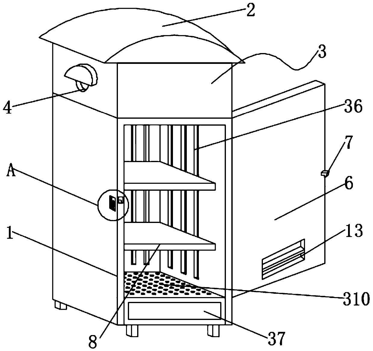
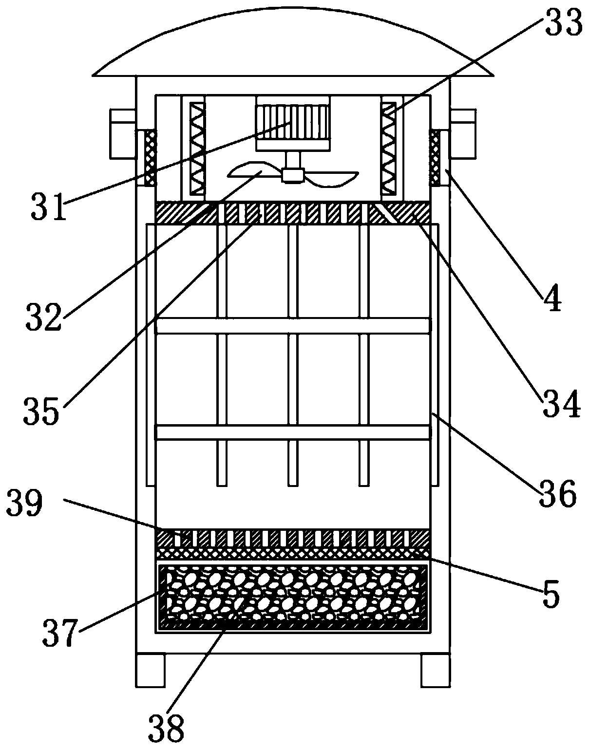
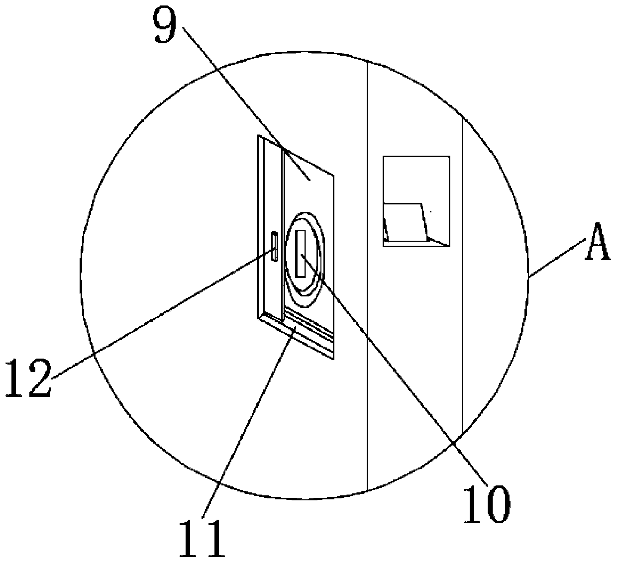
[0019] see Figure 1-3 , the present invention provides a technical solution: an anti-condensation dual-power switch cabinet, including a box body 1, an arc-shaped rain shield 2, a dehumidification and drying component 3, an air inlet 4, a filter screen 5, a door 6, a lock Tongue 7, fixed plate 8, mounting groove 9, lock body 10, chute 11, baffle plate 12 and air outlet 13, are provided with dehumidification drying assembly 3 on the top inner wall of box body ...


PUM


Abstract

The invention discloses an anti-condensation dual-power switch cabinet. The device comprises a box body, an arc-shaped rain baffle, a dehumidifying and drying assembly, an air inlet, a filter screen,a box door, a spring bolt, a fixing plate, a mounting groove, a lock body, a sliding groove, a baffle and an air outlet; a rotating motor is mounted on the middle inner wall of the top end of the boxthrough bolts; one end of an output shaft of the rotating motor is fixedly sleeved with fan blades; electric heating plates are symmetrically and fixedly installed on the inner walls of the top ends of the box body located on the two sides of the fan blades , ventilation plates are fixedly installed on the inner walls of the two sides of the box body located below the electric heating plates , ventilation holes are distributed in the outer walls of the top ends of the ventilation plates in a penetrating mode, and air inducing grooves corresponding to the ventilation holes are distributed in the inner walls of the two sides of the box body. The dehumidifying and drying assembly is simple in structure and convenient to operate, the service life of the switch cabinet is prolonged, safety accidents are not likely to happen, the lock body can be effectively protected through the baffle, the service life of the lock body is prolonged, and the safety of the switch cabinet is improved.

Description

technical field [0001] The invention relates to the technical field of a double power switch cabinet, in particular to a dew-proof double power switch cabinet. Background technique [0002] The switch cabinet is a kind of electrical equipment. The outside line of the switch cabinet first enters the main control switch in the cabinet, and then enters the sub-control switch. Each branch is set according to its needs, such as instruments, automatic control, motor magnetic switches, various AC contactors, etc. Some also have high-voltage room and low-voltage room switchgear, high-voltage busbars, such as power plants, etc., and some also have low-cycle load shedding to ensure the main equipment. When it is different, there will be temperature difference and condensation will appear, which will easily cause accidents and cause losses. In addition, most of the lock body of the switch cabinet is exposed, which is easy to be oxidized by rain and air, which will affect the service li...

Claims


Application Information

Patent Timeline
IPC IPC(8): H02B1/30H02B1/56H02B1/28B01D53/26B01D46/10
CPCB01D46/10B01D53/26H02B1/28H02B1/30H02B1/565
Inventor 黄其昌刘志强
Owner 七星电气股份有限公司
Why Eureka
Try Eureka