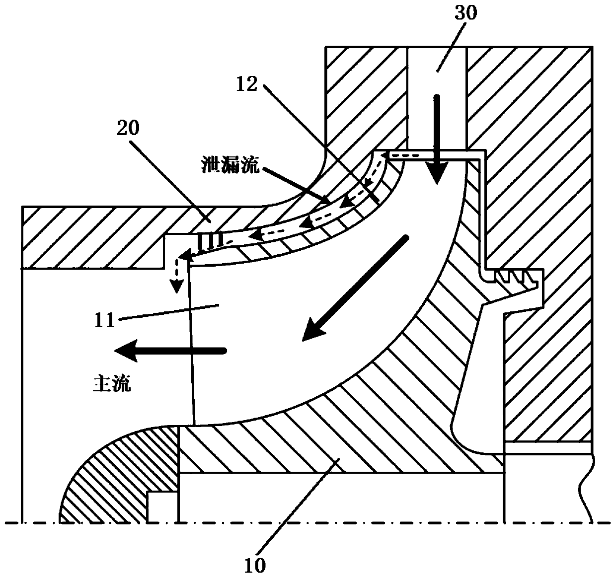
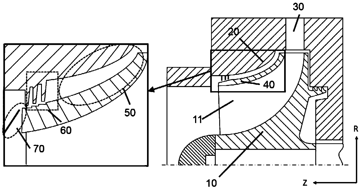
Closed centripetal turbine cover-machine case cavity structure for restraining leakage losses

A closed-type, turbine technology, applied in the direction of mechanical equipment, engine components, machines/engines, etc., can solve the problems that have not been considered, the gap size cannot be too small, and restrictions, etc., to reduce the leakage flow velocity, high energy utilization efficiency, Effect of reducing blending loss

Active Publication Date: 2020-07-24
INST OF ENGINEERING THERMOPHYSICS - CHINESE ACAD OF SCI
View PDF4 Cites 3 Cited by
  • Summary
  • Abstract
  • Description
  • Claims
  • Application Information

AI Technical Summary

Problems solved by technology

[0003] At present, the main technical means to control the leakage flow loss of the centripetal closed impeller cover-casing cavity is to adopt a conventional sealing structure, but this method is affected by the geometric shape of the impeller and the casing, vibration displacement, processing and installation accuracy, installation Influenced by factors such as technology, in order to prevent the collision and friction between the wheel cover and the casing, the gap size cannot be too small in practical applications, and the application is limited
Although there are many sealing technologies for the leakage flow loss of the centripetal closed wheel cover-casing cavity, such as grate seal, brush seal, honeycomb seal, etc., the above structure does not consider the flow parameters when the upstream leakage flow enters the seal (speed, direction, etc.), and the speed and direction of further mixing of the leakage flow and the mainstream after the outflow seal is not considered, which limits the effect of loss control

Method used


Image

  • Closed centripetal turbine cover-machine case cavity structure for restraining leakage losses
  • Closed centripetal turbine cover-machine case cavity structure for restraining leakage losses
  • Closed centripetal turbine cover-machine case cavity structure for restraining leakage losses

Examples


Embodiment Construction

[0032] In order to make the objectives, technical solutions and advantages of the present invention clearer, the technical solutions in the embodiments of the present invention will be described in more detail below in conjunction with the drawings in the embodiments of the present invention. In the drawings, the same or similar reference numerals denote the same or similar elements or elements having the same or similar functions throughout. The described embodiments are some, but not all, embodiments of the invention. The embodiments described below by referring to the figures are exemplary and are intended to explain the present invention and should not be construed as limiting the present invention. Based on the embodiments of the present invention, all other embodiments obtained by persons of ordinary skill in the art without creative efforts fall within the protection scope of the present invention. The structure and technical solutions of the present invention will be ...


PUM


Abstract

The invention relates to a closed centripetal turbine cover-machine case cavity structure for restraining leakage losses, and the closed centripetal turbine cover-machine case cavity structure is suitable for a compressed air energy storage system. An expansion runner, a seal structure and a leakage flow mixing restraining structure are sequentially arranged in a narrow and long cavity formed between a front wheel cover and a machine case. The circulation area of the expansion runner is gradually increased in the flowing direction. The leakage flow mixing restraining structure is a shielding sheet from a cavity outlet to a seal outlet. On the basis of leakage flow control through a conventional seal structure, the inlet leakage flow can be reduced through the cavity expansion runner, leakage flow and main flow mixing losses are further reduced through leakage flow mixing restraining, finally, the pneumatic efficiency and the acting capability of a turbine are improved, and the rate ofutilization of energy through the turbine is increased. The closed centripetal turbine cover-machine case cavity structure can be widely applied to aerospace, transportation, petrochemical engineering, energy power and other multiple fields besides compressed air energy storage and is particularly suitable for high-pressure radial-flow turbines.

Description

technical field [0001] The invention relates to the field of radial flow turbines in fluid machinery, and relates to a structure for suppressing the leakage flow loss of a closed centripetal turbine wheel cover-casing cavity, in particular to a closed centripetal turbine that couples multiple structures Wheel cover-casing cavity structure. Background technique [0002] In recent years, centripetal turbines using the energy of gaseous working medium have been widely used and have various structural types to provide electricity and power for industrial production and public life. In order to make a unit volume of equipment output as much mechanical energy as possible under the same thermal parameters, it is necessary to improve the efficiency of the centripetal turbine. As a kind of rotating machinery, the wheel cover of the closed impeller of the centripetal turbine and the casing have relative motion, and there must be a cavity between the two, and this cavity structure mak...

Claims


Application Information

Patent Timeline
Patent Type & Authority Applications(China)
IPC IPC(8): F01D5/04
CPCF01D5/048
Inventor 王星张雪辉朱阳历李文陈海生
Owner INST OF ENGINEERING THERMOPHYSICS - CHINESE ACAD OF SCI
Why Eureka
Try Eureka