Robot signal transmission system

A signal transmission system and robot technology, applied in the field of robots, can solve the problems of robot operation command error, increase the depth of signal attenuation, and redundancy, etc.

Inactive Publication Date: 2020-07-24
ZHENGZHOU INST OF TECH
View PDF0 Cites 7 Cited by
  • Summary
  • Abstract
  • Description
  • Claims
  • Application Information

AI Technical Summary

Problems solved by technology

[0002] A robot is a common name for an automatic control machine (Robot). Automatic control machines include all machines that simulate human behavior or thoughts and simulate other creatures. With the rapid development of modern computer technology, robots are playing an increasingly important role in people's life processes. tasks, and at the same time face a variety of complex working environ...

Method used


Image

  • Robot signal transmission system

Examples


Embodiment 1

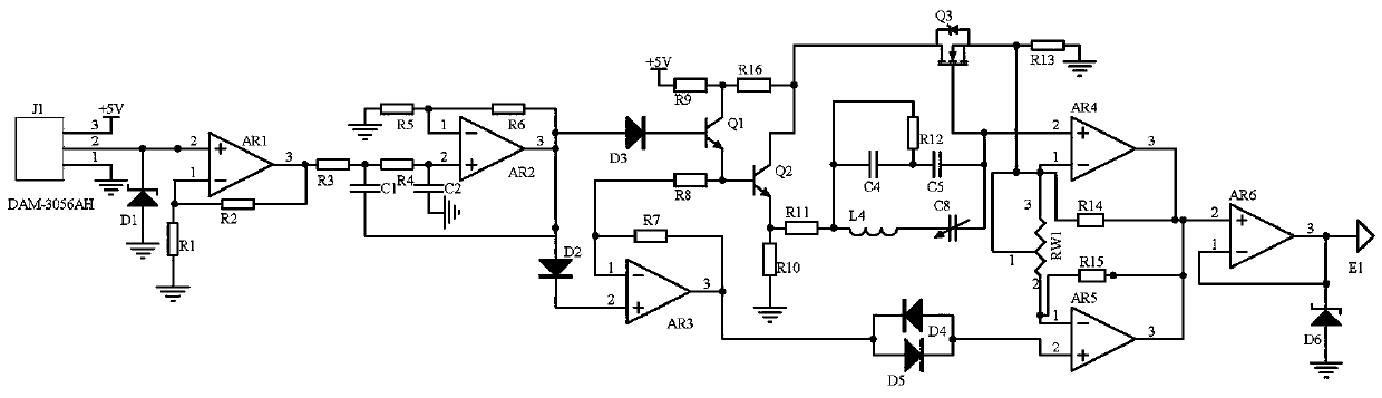
[0011] Embodiment 1: A robot signal transmission system includes a signal sampling module and a noise reduction differential module. The signal sampling module uses a signal sampler J1 model DAM-3056AH to sample the signal of the signal transmitter in the robot signal transmission system. The output terminal of the sampling module is connected to the input port of the noise reduction differential module, and the noise reduction differential module sends a signal to the terminal of the robot signal transmission system;

[0012] The noise reduction differential module uses op amp AR2, capacitor C1 and capacitor C2 to form a noise reduction circuit to reduce signal noise. Capacitor C1 plays a decoupling role to reduce the noise of the signal at the non-inverting input of op amp AR2, and uses capacitor C2 Filter out the signal clutter, the operational amplifier AR2 amplifies the signal power to ensure the signal strength and realize the effect of noise reduction, and then adjust the s...

Embodiment 2

[0014] In the second embodiment, on the basis of the first embodiment, the signal sampling module selects the signal sampler J1 model DAM-3056AH, uses the operational amplifier AR1 to amplify the signal in phase, and the power supply of the signal sampler J1 is connected to the power supply +5V, The ground terminal of the signal sampler J1 is grounded, the output terminal of the signal sampler J1 is connected to the negative terminal of the voltage regulator tube D1, the non-inverting input terminal of the operational amplifier AR1, the positive terminal of the voltage regulator tube D1 is grounded, and the inverting input terminal of the operational amplifier AR1 Connect one end of resistor R1 and resistor R2, the other end of resistor R1 is grounded, the output end of operational amplifier AR1 is connected to the other end of resistor R2 and one end of resistor R3, and the other end of resistor R3 is connected to the signal input port of the noise reduction differential module....


PUM


Abstract

The invention discloses a robot signal transmission system. The system comprises a signal sampling module and a noise reduction differential module. The signal sampling module uses a signal sampler J1with a model of DAM-3056AH to sample signals of a signal emitter in a robot signal transmission system. The output end of the signal sampling module is connected with the input port of the noise reduction differential module; the noise reduction differential module sends a signal to a robot signal transmission system terminal; the noise reduction differential module uses a diode D4 and a diode D5to form an amplitude limiting circuit protection signal. Finally, a differential circuit composed of an operational amplifier AR4 and an operational amplifier AR5 and a variable resistor RW1 carriesout differential processing on the two paths of signals. Common-mode interference is suppressed, the output signal amplitude of the differential circuit can be adjusted by adjusting the loop resistance value of the variable resistor RW1, then the signal emitter E1 is triggered to work after signals are buffered through the operational amplifier AR6, a robot signal transmission system terminal canconveniently adjust the signal data size of the signal emitter in time, and the signal attenuation depth is reduced.

Description

Technical field [0001] The invention relates to the technical field of robots, in particular to a robot signal transmission system. Background technique [0002] Robot is the common name of automatic control machine (Robot). Automatic control machine includes all the machinery that simulates human behavior or thought and simulates other living things. With the rapid development of modern computer technology, robots are becoming more and more important in people's lives. At the same time, facing various complex working environments, robots need to perform more precise operations, and the robot signal transmission system needs to transmit more complicated signals, and the carrier signal will be attenuated during transmission. Once the signal transmission data is over at a certain moment Larger, it will increase the depth of signal attenuation, resulting in larger errors in robot operation commands, and seriously affecting the efficiency of robot operations. Summary of the inventio...

Claims


Application Information

Patent Timeline
IPC IPC(8): H04B1/04
CPCH04B1/04H04B1/0475H04B2001/0408
Inventor 孔国利许绘香王哲
Owner ZHENGZHOU INST OF TECH
Why Eureka
Try Eureka