Redox flow battery

A flow battery and battery cell technology, applied in fuel cells, regenerative fuel cells, fuel cell grouping, etc., can solve problems such as increased fluid flow resistance pumping loss, uneven performance of battery cells, and decreased efficiency, and achieves a reduction in or The effect of shunt current, power saving and efficiency improvement

Active Publication Date: 2020-07-24
STANDARD ENERGY CO LTD
View PDF9 Cites 0 Cited by
  • Summary
  • Abstract
  • Description
  • Claims
  • Application Information

AI Technical Summary

Problems solved by technology

However, the electrolyte filled in the multi-manifold acts as an electrical channel connecting each battery cell, so it can become a moving path for electrons. Through such a path, a shunt current is generated, so a part of the energy is lost when charging and discharging. Loss due to shunt current, which is the main cause of efficiency drop, component damage, and uneven cell performance
In the past, in order to reduce such shunt current, the method of increasing the length of the manifold and reducing the cross-sectional area was mainly used, but this would increase the flow resistance of the fluid and cause pumping loss, so solutions that can overcome this problem are required plan

Method used


Image

  • Redox flow battery
  • Redox flow battery
  • Redox flow battery

Examples


Embodiment 1

[0182] (Example 1, Comparative Examples 1 to 2)

[0183] There are 10 fluid control parts in total, and they are connected to one pressure generator, and two fluid control parts are respectively connected to one electrolyte tank. Then, the flow rate of the electrolytic solution transferred through each fluid control unit was measured one by one. At this time, when the maximum volume V of the electrolyte is h and the reaction volume of the electrolyte V c The ratios of the ratios were adjusted to 0.05 (embodiment 1), 0.02 (comparative example 1), and 20 (comparative example 2) to measure flow deviation ratios and record them in Figure 14 and Table 1.

[0184] [Table 1]

[0185] V h / V c

Flow Deviation Ratio Example 1 0.05 0.05 Comparative example 1 0.02 1.0 Comparative example 2 20 0.05

[0186] When the flow rate deviation ratio is 1, it means that at least one fluid control unit among the plurality of fluid control units cannot...

Embodiment 2

[0190] In order to measure the critical flow rate, the conditions are set to be the same as in Example 1, and since the average flow rate per minute is V c Experiments were carried out in the range of 3000% from 0.5% of the battery cell, and the change in efficiency of the battery cell was measured. In this range, the efficiency deviation ratio calculated according to Equation 4 is shown in a graph. At this time, since the average flow per minute is V c Values ​​ranging from 0.5% to 10% are shown graphically because there is no significant difference in the resulting values ​​above 10%.

[0191] As shown in (c) of Figure 14, it was confirmed that the critical flow rate is V when the electrolyte solution flows per minute. c When more than 3% of the battery cell efficiency deviation is greatly reduced. Therefore, the preferred critical flow rate is V c 3% or more.


PUM


Abstract

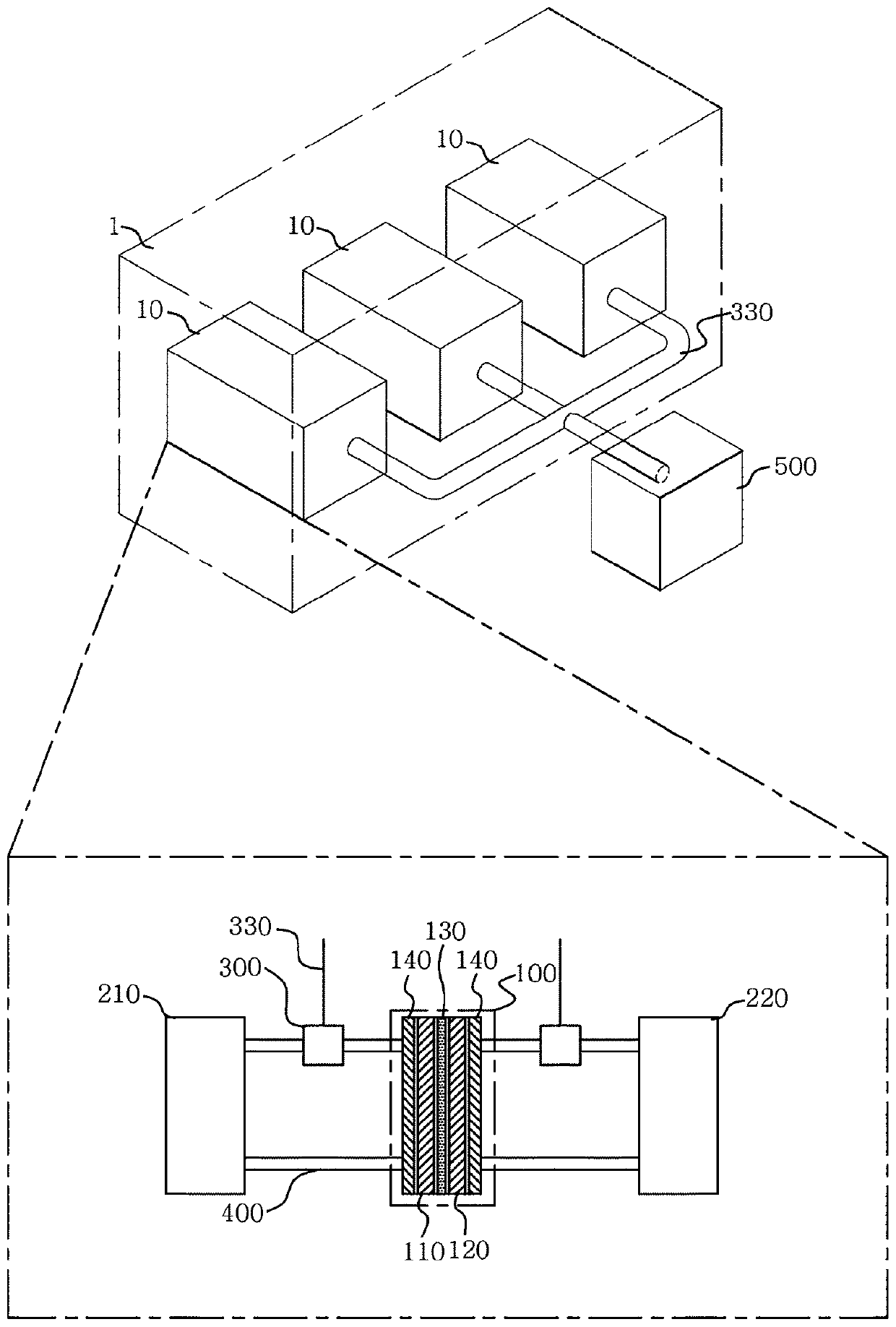
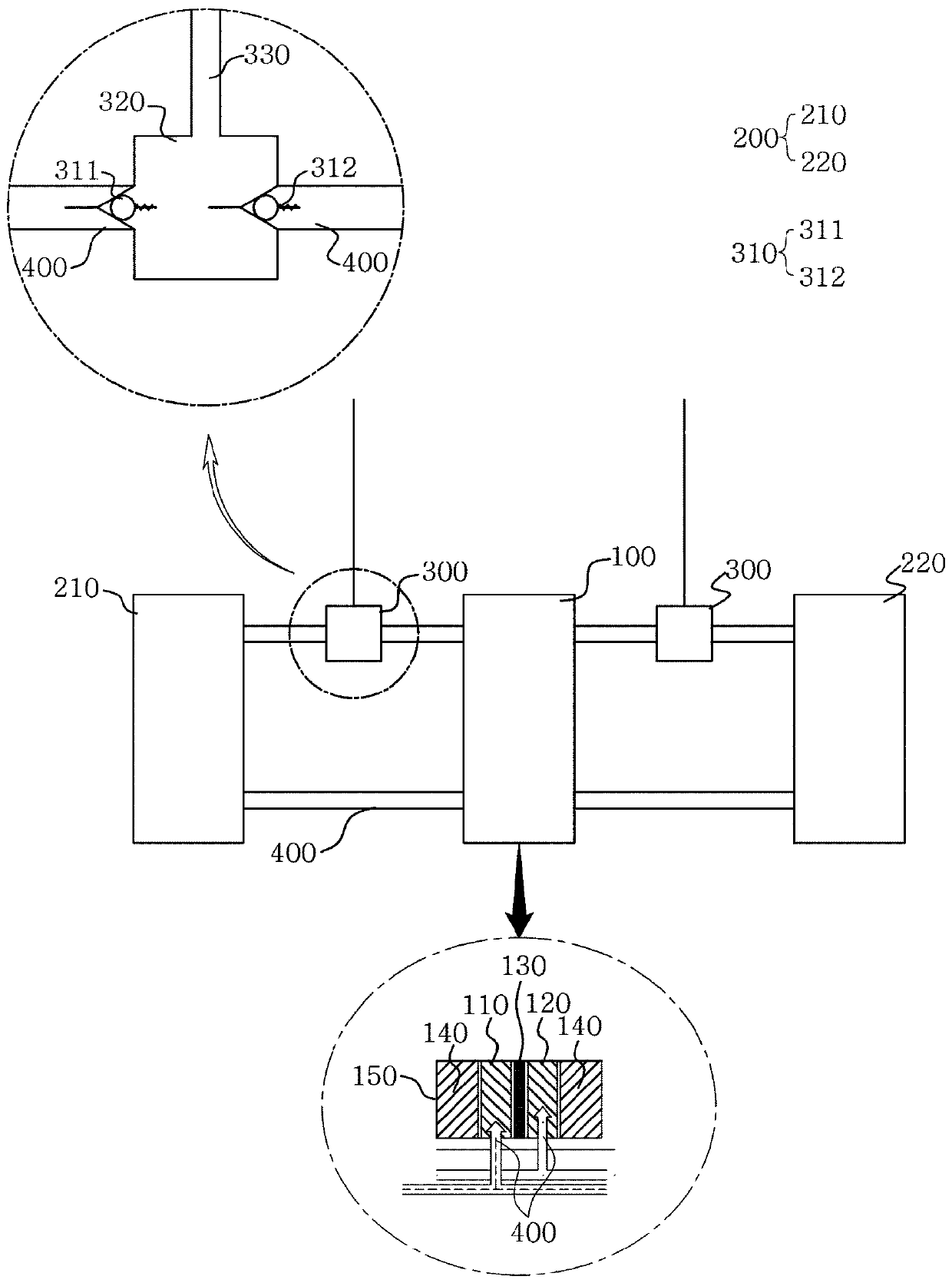
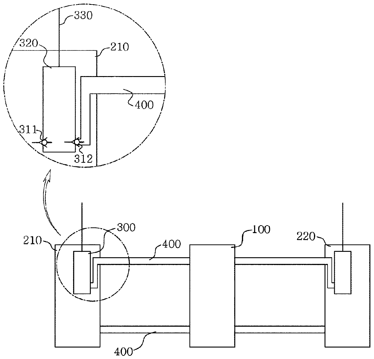
A redox flow battery according to the present invention includes a battery module having, therein, battery cells or a stack and an electrolyte tank, and applies, to each battery module, a means for replacing a pump so as to transport the electrolyte to the battery cell or the stack, thereby significantly reducing the occurrence of a shunt current. In addition, a transfer path of the electrolyte can be rapidly reduced by providing an electrolyte tank for each battery module, and the power, which is required for operating the pump, can be saved by providing a fluid control unit using pressure, instead of providing the pump for each module, in order to transport the electrolyte, thereby enhancing battery efficiency.

Description

technical field [0001] The present invention relates to a redox flow battery. Specifically, it relates to a redox flow battery combined with a plurality of battery modules. The electrolyte tank for the electrolyte and the fluid control unit for transferring the electrolyte from the electrolyte tank to the battery core can shorten the reaction time, improve the efficiency, and suppress the generation of shunt current. Background technique [0002] Recently, energy-saving energy sources such as solar energy and wind energy have been favored as a method for suppressing emission of greenhouse gases, which is a major cause of global warming, and a lot of research is being conducted for their practical use. However, renewable energy is greatly affected by the site selection environment and natural conditions. In particular, since the output of renewable energy fluctuates greatly, there is a disadvantage that energy cannot be supplied continuously and uniformly. Therefore, in ord...

Claims


Application Information

Patent Timeline
Patent Type & Authority Applications(China)
IPC IPC(8): H01M8/04276H01M8/24H01M8/2455H01M8/18
CPCH01M8/04276H01M8/188Y02E60/50H01M8/2455H01M8/2459
Inventor 金富基金箕贤朴相炫崔淡潭赵范熙崔康永
Owner STANDARD ENERGY CO LTD
Why Eureka
Try Eureka