A CNC turning machining center equipment

A machining center and turning technology, applied in metal processing equipment, metal processing machinery parts, manufacturing tools, etc., can solve the problems of blocked translation of nut pairs, high cleaning costs, waste of screw rods, etc., to achieve smooth translation and reduce maintenance Low cost, smooth and unimpeded rotation

Active Publication Date: 2021-03-12
东莞市迪奥数控设备有限公司
View PDF12 Cites 0 Cited by
  • Summary
  • Abstract
  • Description
  • Claims
  • Application Information

AI Technical Summary

Problems solved by technology

[0002] The CNC turning machining center equipment can process various rotating surfaces, such as inner and outer cylindrical surfaces, inner and outer conical surfaces, threads, grooves, end faces and forming surfaces, etc. The machining accuracy can reach IT8-IT7, and the surface roughness Ra value is 1.6-0.8. Turning is often used to process parts with a single axis. The screw rods of the existing CNC turning machining center equipment are exposed to the outside. The screw rods are not only easy to oxidize and rust if they are exposed for a long time, they will also be covered with dust to form dirt, which will affect the translation of the nut pair. Accuracy, which will affect the precision of the turning process. At the same time, the screw rod with accumulated dirt needs to be disassembled for cleaning, and the cleaning difficulty is relatively high, and the cleaning cost is high. In addition, the rusted screw rod will hinder the translation of the nut pair, so It will lead to the waste of the screw rod, which will increase the maintenance cost

Method used


Image

  • A CNC turning machining center equipment
  • A CNC turning machining center equipment
  • A CNC turning machining center equipment

Examples


Embodiment 1

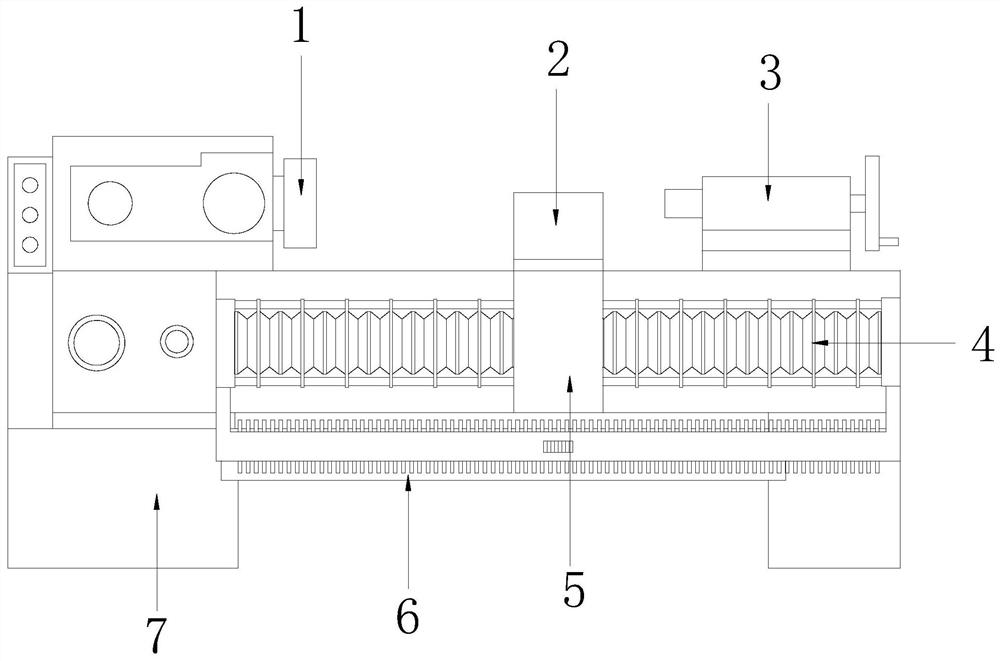
[0033] see figure 1 , the present invention provides a technical solution for CNC turning machining center equipment: its structure includes a fixed chuck 1, a turning device 2, a moving chuck device 3, a moving device 4, a moving seat 5, a water receiving tray 6, and a body 7. The body 7. A fixed chuck 1 is provided on one side, and a movable clamp device 3 is installed on the other side. A turning device 2 is provided between the fixed chuck 1 and the movable clamp device 3, and the turning device 2 is connected to the moving seat 5. The moving seat 5 is connected to the moving device 4, and the moving device 4 is connected to the body 7, and the body 7 is also equipped with a water receiving tray 6;

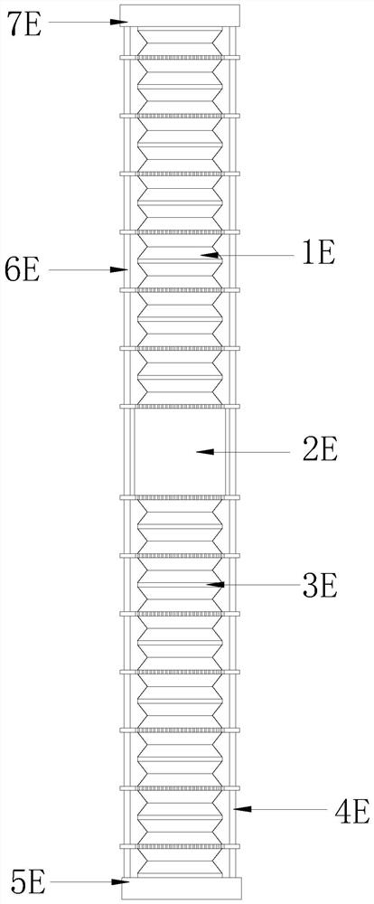
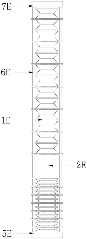
[0034] see Figure 2-5 , the moving device 4 includes a No. 1 bellows 1E, a nut pair 2E, a No. 2 bellows 3E, a No. 1 guide rod 4E, a No. 2 fixing seat 5E, a No. 2 guide rod 6E, a No. 1 fixing seat 7E, and a screw rod 8E , one end of the screw rod 8E is connected to the No. ...

Embodiment 2

[0037] see figure 1 , the present invention provides a technical solution for CNC turning machining center equipment: its structure includes a fixed chuck 1, a turning device 2, a moving chuck device 3, a moving device 4, a moving seat 5, a water receiving tray 6, and a body 7. The body 7. A fixed chuck 1 is provided on one side, and a movable clamp device 3 is installed on the other side. A turning device 2 is provided between the fixed chuck 1 and the movable clamp device 3, and the turning device 2 is connected to the moving seat 5. The moving seat 5 is connected to the moving device 4, and the moving device 4 is connected to the body 7, and the body 7 is also equipped with a water receiving tray 6;

[0038] see Figure 2-5 , the moving device 4 includes a No. 1 bellows 1E, a nut pair 2E, a No. 2 bellows 3E, a No. 1 guide rod 4E, a No. 2 fixing seat 5E, a No. 2 guide rod 6E, a No. 1 fixing seat 7E, and a screw rod 8E , one end of the screw rod 8E is connected to the No. ...


PUM


Abstract

The invention discloses a numerical control turning machining center equipment, the structure of which comprises a fixed chuck, a turning device, a moving clamp device, a moving device, a moving seat, a water tray, and a machine body. One side of the machine body is provided with a fixed chuck, and the other side A movable clamp device is installed, and a turning device is provided between the fixed chuck and the movable clamp device. Compared with the prior art, the beneficial effect of the present invention is that: through the No. 1 bellows, the nut pair, the No. 2 bellows, the No. 1 The combination of guide rod, No. 2 fixed seat, No. 2 guide rod, No. 1 fixed seat, screw rod, and screw cooling mechanism can hide the screw rod to prevent the screw rod from being exposed to oxidation and rust. It avoids dust and impurities from sticking to form dirt, so that the screw rod does not need to be cleaned, which greatly reduces maintenance costs. At the same time, it makes the translation of the nut pair smooth and unimpeded, which is conducive to improving the accuracy of the translation of the nut pair, and can dissipate heat from the screw rod to avoid thermal expansion of the screw rod body. It affects the translation of the nut pair, which is helpful for the turning precision.

Description

technical field [0001] The invention relates to the technical field of numerical control turning processing, in particular to a numerical control turning machining center equipment. Background technique [0002] The CNC turning machining center equipment can process various rotating surfaces, such as inner and outer cylindrical surfaces, inner and outer conical surfaces, threads, grooves, end faces and forming surfaces, etc. The machining accuracy can reach IT8-IT7, and the surface roughness Ra value is 1.6-0.8. Turning is often used to process parts with a single axis. The screw rods of the existing CNC turning machining center equipment are exposed to the outside. The screw rods are not only easy to oxidize and rust if they are exposed for a long time, they will also be covered with dust to form dirt, which will affect the translation of the nut pair. Accuracy, which will affect the precision of the turning process. At the same time, the screw rod with accumulated dirt nee...

Claims


Application Information

Patent Timeline
Patent Type & Authority Patents(China)
IPC IPC(8): B23Q11/08B23Q11/12
CPCB23Q11/0816B23Q11/126
Inventor 袁克月钟金梅
Owner 东莞市迪奥数控设备有限公司
Why Eureka
Try Eureka