Superposed assembly type structure subway station and assembly construction method thereof

A prefabricated, subway station technology, applied in infrastructure engineering, underwater structures, artificial islands, etc., can solve problems such as environmental water pollution, noise pollution, air pollution, etc., achieve support system optimization, reduce site demand, reduce The effect of site occupancy

Pending Publication Date: 2020-07-28
CCCC FIRST HARBOR ENG +2
View PDF0 Cites 9 Cited by
  • Summary
  • Abstract
  • Description
  • Claims
  • Application Information

AI Technical Summary

Problems solved by technology

Wet cast-in-place operation will also cause environ...

Method used


Image

  • Superposed assembly type structure subway station and assembly construction method thereof
  • Superposed assembly type structure subway station and assembly construction method thereof
  • Superposed assembly type structure subway station and assembly construction method thereof

Examples


Embodiment 1

[0058] Introduction to Structural Node Connections

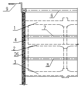
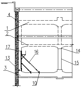
[0059] A superimposed prefabricated structure subway station, which consists of: a roof 1, a middle plate 2, a bottom plate 3, a side wall 4 and a heat exhaust air duct 5, and the structural nodes are connected:

[0060] Bottom plate and side wall connection

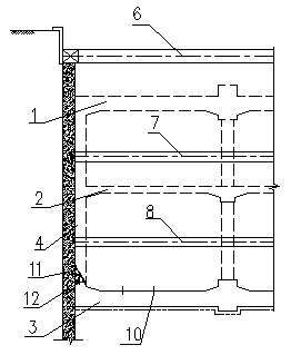
[0061] (1) The construction joint 12 from the bottom plate to the bottom of the negative second floor is a cast-in-place reinforced concrete structure, and the leaking grouting sleeve 13 is pre-embedded at the construction joint to connect the stressed steel bars of the upper side wall;

[0062] (2) The inner skin of the side wall is a prefabricated block with truss bars (both the stress bars and the distribution bars are carried), and at the same time, it is used as the inner formwork, the bottom is inserted into the grouting sleeve, and the stress bars are connected by pouring high-efficiency grouting materials. The width of the longitudinal block About 2m, strength...

Embodiment 2

[0065] Middle plate and side wall connection

[0066] (1) The concrete of the side wall of the negative second floor is poured to the construction joint at the top of the negative second floor, and a steel bar connector is reserved for the stressed steel bar of the side wall at the construction joint to connect the upper steel bar;

[0067] (2) The bottom skin of the middle slab is a prefabricated block with truss reinforcement, which is also used as a template for the bottom skin. The width of the longitudinal block is about 2m. Reinforcement connection holes for later installation of heat exhaust air duct;

[0068] (3) The concrete of the middle slab is poured to the construction joint at the bottom of the negative floor to form a superimposed structure of the middle slab, and the leaking grouting sleeve is pre-embedded at the joint to connect the stressed steel bars of the upper side wall;

Embodiment 3

[0070] Roof and side wall connection

[0071] (1) The concrete of the side wall of the negative first floor is poured to the construction joint at the top of the negative first floor, and a steel bar connector is reserved for the stressed steel bar of the side wall at the construction joint to connect the upper steel bar;

[0072] (2) The bottom skin of the roof is a prefabricated block with truss reinforcement, which is also used as a bottom skin formwork. The width of the block is about 2m.

[0073] (3) The roof concrete is poured to form a roof superimposed structure.


PUM


Abstract

The invention relates to a superposed assembly type structure subway station and an assembly construction method thereof. At present, when the station construction is carried out, a large number of formworks are needed, the field operation amount is large, and the construction period is long; environmental water pollution, noise pollution and air pollution can also be caused by the cast-in-place wetting operation, the superposed assembly type structure subway station comprises a top plate (1), a middle plate (2), a bottom plate (3), a heat exhaust air duct (5) and a side wall (4), and is characterized in that a construction joint from the bottom plate to the bottom of a negative second layer is of a cast-in-place reinforced concrete structure, and an exposed grouting sleeve is pre-buried at the construction joint and is connected with an upper side wall stress steel bar; the side wall inner skin is a precast block with truss bars and serves as an inner side formwork at the same time, the bottom of the side wall inner skin is inserted into the grouting sleeve, the stress steel bars are connected by pouring efficient grouting materials, a cast-in-place belt is arranged on the construction joint, side wall cavity concrete is poured, and a side wall overlapping structure is formed. The method thereof is applied to the field of subway construction.

Description

Technical field: [0001] The invention relates to a superimposed assembly type structure subway station and an assembly construction method. Background technique: [0002] Excavation methods for subway underground stations mainly include open-cut method, cover-excavation method, and shallow-buried underground excavation method. When various excavation methods are involved in the construction of subway underground station structures, the side walls, columns, bottom plates, middle plates, roof plates and other structures of the station structure often adopt the methods of on-site support formwork, on-site pouring concrete, and on-site maintenance. This cast-in-place construction method has the advantages of good integrity, high rigidity, and good shock resistance. However, there are obvious disadvantages in adapting to the construction site schedule and green construction requirements. Not only does it require a large number of templates, but also requires a large amount of w...

Claims


Application Information

Patent Timeline
IPC IPC(8): E02D29/045E02D29/16E02D31/02
CPCE02D29/04E02D29/16E02D31/02
Inventor 权县民刘运生梁宇石立民聂善军吴天林黄海龙王小军张强黄磊
Owner CCCC FIRST HARBOR ENG
Why Eureka
Try Eureka