High-frequency torque oscillator
An oscillator and torque technology, which is applied in the direction of drilling with vibration, can solve the problems of limited use range, high processing accuracy requirements, high difficulty, short service life, etc., and achieves remarkable speed-up effect, low cost of use, and remarkable effect.
- Summary
- Abstract
- Description
- Claims
- Application Information
AI Technical Summary
Problems solved by technology
Method used
Image
Examples
Embodiment 1
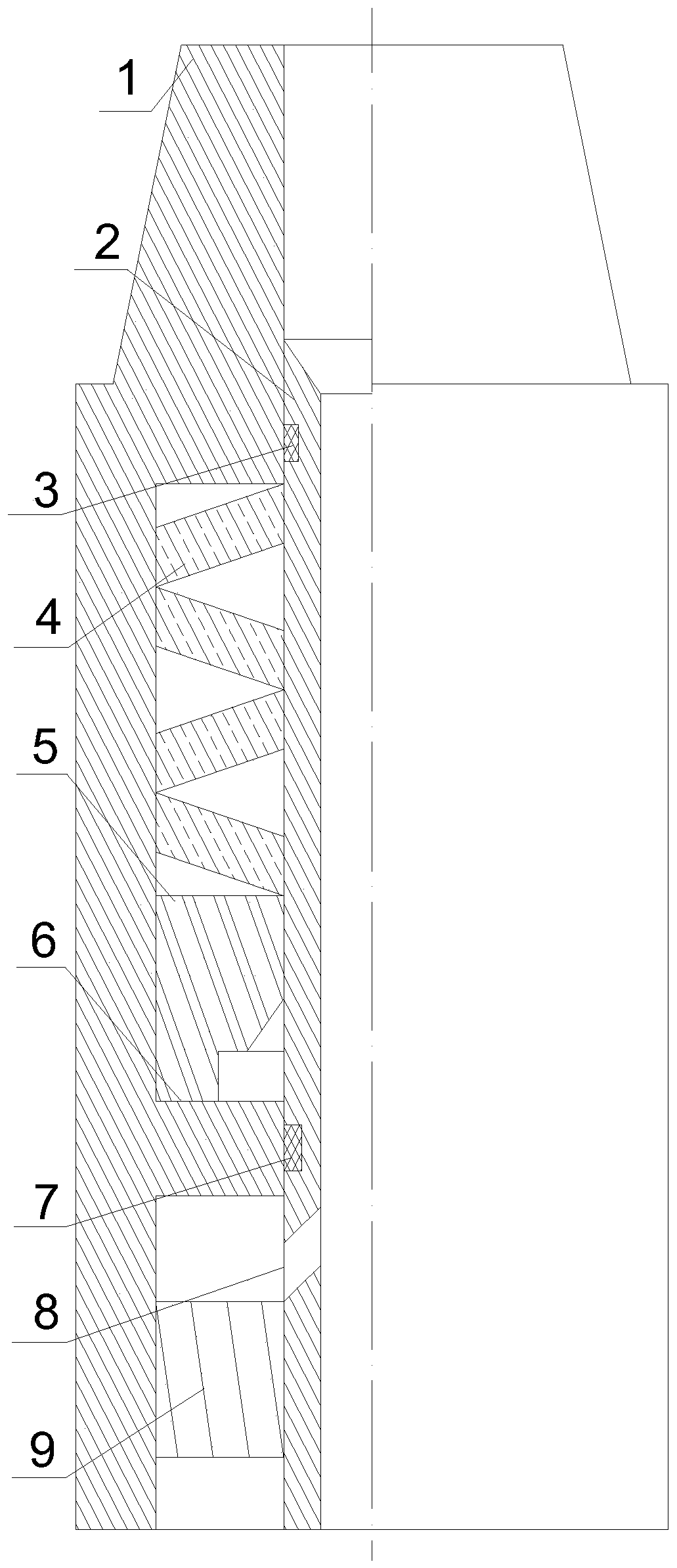
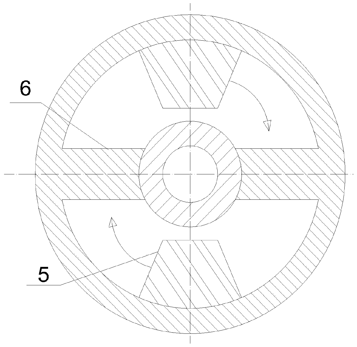
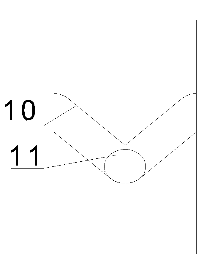
[0024] Refer to attached Figure 1-8 , a high-frequency torque oscillator, including an outer shell 1, a central shaft 2, a spring device 4, a hammer 5, an anvil 6 and a turbine 9, wherein: the central shaft 2 is installed inside the outer shell 1, and the central shaft 2. There is a central channel in the axial direction, and a chute 10 is provided on the outer wall of the central shaft 2. A sliding guide ball 11 is placed in the chute 10. A groove 12 is provided on the hammer 5. The groove 12 is slidably matched with the guide ball 11. The hammer 5 is installed on the central shaft 2, and forms sliding and rotating cooperation with the central shaft 2 through the guide ball 11; the spring device 4 is arranged between the upper part of the hammer 5 and the outer shell 1, and the anvil 6 is arranged at the lower part of the hammer 5 In the outer casing 1, under the action of the spring device 4, the hammer 5 contacts and cooperates with the anvil 6, and the anvil 6 is limited ...
Embodiment 2
[0028] Refer to attached Figures 1 to 4 , The high-frequency torque oscillator is mainly composed of an outer shell 1, a central shaft 2, an upper sealing device 3, a spring device 4, a hammer 5, an anvil 6, a lower sealing device 7, a bypass hole 8, a turbine 9, and a chute 10 , Guide ball 11, groove 12 are formed. The central shaft 2 is installed inside the casing 1, and a sealing device 3 is installed between the two. A chute 10 is processed on the central shaft 2. The chute 10 is V-shaped, and a guide ball 11 is placed in the chute 10 . The hammer 5 is provided with a groove 12, the groove 12 is in an inverted V shape, and a guide ball 11 is placed in the groove 12, the hammer 5 is installed on the central shaft 2, and cooperates with the central shaft 2 through the guide ball 11. A spring device 4 is installed between the hammer 5 and the outer shell 1, and an anvil 6 is installed inside the outer shell 1. Under the action of the spring device 4, the hammer 5 and the an...
PUM
 Abstract
Description
Claims
Application Information
 - R&D
- Intellectual Property
- Life Sciences
- Materials
- Tech Scout
- Unparalleled Data Quality
- Higher Quality Content
- 60% Fewer Hallucinations
Browse by: Latest US Patents, China's latest patents, Technical Efficacy Thesaurus, Application Domain, Technology Topic, Popular Technical Reports.
© 2025 PatSnap. All rights reserved.Legal|Privacy policy|Modern Slavery Act Transparency Statement|Sitemap|About US| Contact US: help@patsnap.com


