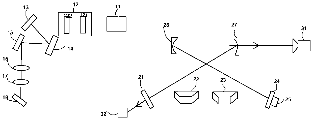
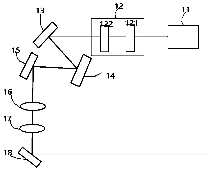
Non-destructive vortex light field beam splitting device
A vortex light, non-destructive technology, applied in the fields of laser technology, nonlinear photophysics, atomic physics, can solve the problems of original state destruction, low efficiency, etc., to achieve the effect of improving purity and good imaging effect
- Summary
- Abstract
- Description
- Claims
- Application Information
AI Technical Summary
Problems solved by technology
Method used
Image
Examples
Embodiment A
[0071] Embodiment A is specifically as follows: R 4 =0.95, T=0.98, the transmittance T of the annular cavity, and the transmittance T of the output coupling mirror 27 4 and the phase δ of the intracavity beam propagation of the annular cavity is fixed, by adjusting the reflectivity R of the input coupling mirror 21 1 , to obtain the reflection coefficient C of the ring cavity as shown in Figure 5(a) R and transmission coefficient C T with the reflectivity R of the input coupling mirror 21 1 relationship curve.
[0072] From Figure 5(a), the transmission coefficient C of the annular cavity R Reaching the minimum value, the reflection coefficient C of the annular cavity T Reaches the maximum value. R in Figure 5(a) 1 becomes larger, the impedance mismatch of the device increases, and the transmission coefficient C of the annular cavity T value decreases, the reflection coefficient of the annular cavity C R The value is increasing. The transmittance of the input couplin...
Embodiment b
[0073] Embodiment b is specifically as follows: R 1 =R 4 =0.90, T=1, as shown in Figure 5(b), this embodiment simulates when the ring cavity resonates with |1>, the input mode is ), the reflection coefficient C of the annular cavity with different phase transformation ΔΦ R and transmission coefficient C T pattern shape. In this example, the language of quantum mechanics is used to represent different OAM modes, defining When ΔΦ increases, the transmission spectra of the modes |1> and |-1> split from the degenerate state to the non-degenerate state, and when the transmission spectra of the two modes are completely separated, the transmission mode only contains the mode resonant with the ring cavity, The other mode is fully reflective.
Embodiment c
[0074] Embodiment c is specifically as follows: for the input mode is ), when the mode matching coefficient M (the mode matching coefficient is the overlapping ratio of the input mode and the cavity eigenmode) varies from 0 to 0.995, the spatial shape of the transmitted and reflected beams is shown in Figure 5(c). When M=0 When , both modes of light are completely reflected, and no mode of light is transmitted from the cavity; while for almost perfect mode matching M = 0.995, one mode of light is completely reflected, and the other mode of light is completely transmitted.
[0075] The experimental and simulation results of the present invention for other different input modes are shown in FIG. 6 . The input modes are the transmission spectra of |0>+|1>, |1>+|2>, |-1>+|1> and |-2>+|2>, such as Figure 6(a)-6(d) shown in . For high topologically charged OAM modes, more irrelevant high-cavity modes will appear in the transmission spectrum due to the impurities of the input mod...
PUM
 Abstract
Description
Claims
Application Information
 - R&D
- Intellectual Property
- Life Sciences
- Materials
- Tech Scout
- Unparalleled Data Quality
- Higher Quality Content
- 60% Fewer Hallucinations
Browse by: Latest US Patents, China's latest patents, Technical Efficacy Thesaurus, Application Domain, Technology Topic, Popular Technical Reports.
© 2025 PatSnap. All rights reserved.Legal|Privacy policy|Modern Slavery Act Transparency Statement|Sitemap|About US| Contact US: help@patsnap.com


