
Centroid identification and positioning method of infrared light spot image

A technology of identification and positioning, infrared light, applied in image enhancement, image analysis, image data processing and other directions, can solve the problems of insufficient accuracy of identifying and positioning the centroid of the infrared spot image, and the time storage cost of the centroid positioning and identification algorithm is large, so as to achieve good spot extraction. The effect of contour, fast calculation speed and strong anti-noise ability

Active Publication Date: 2020-07-28
UNIV OF ELECTRONICS SCI & TECH OF CHINA
View PDF10 Cites 18 Cited by
  • Summary
  • Abstract
  • Description
  • Claims
  • Application Information

AI Technical Summary

Problems solved by technology

[0005] The technical problem to be solved by the present invention is to overcome the lack of accuracy of the existing algorithm for identifying and positioning the centroid of infrared spot images and the problem that the time storage cost of complex centroid positioning and identification algorithms is large, and the design provides a fast sub-pixel precision centroid of spot images Identification and positioning method

Method used


Image

  • Centroid identification and positioning method of infrared light spot image
  • Centroid identification and positioning method of infrared light spot image
  • Centroid identification and positioning method of infrared light spot image

Examples


Embodiment

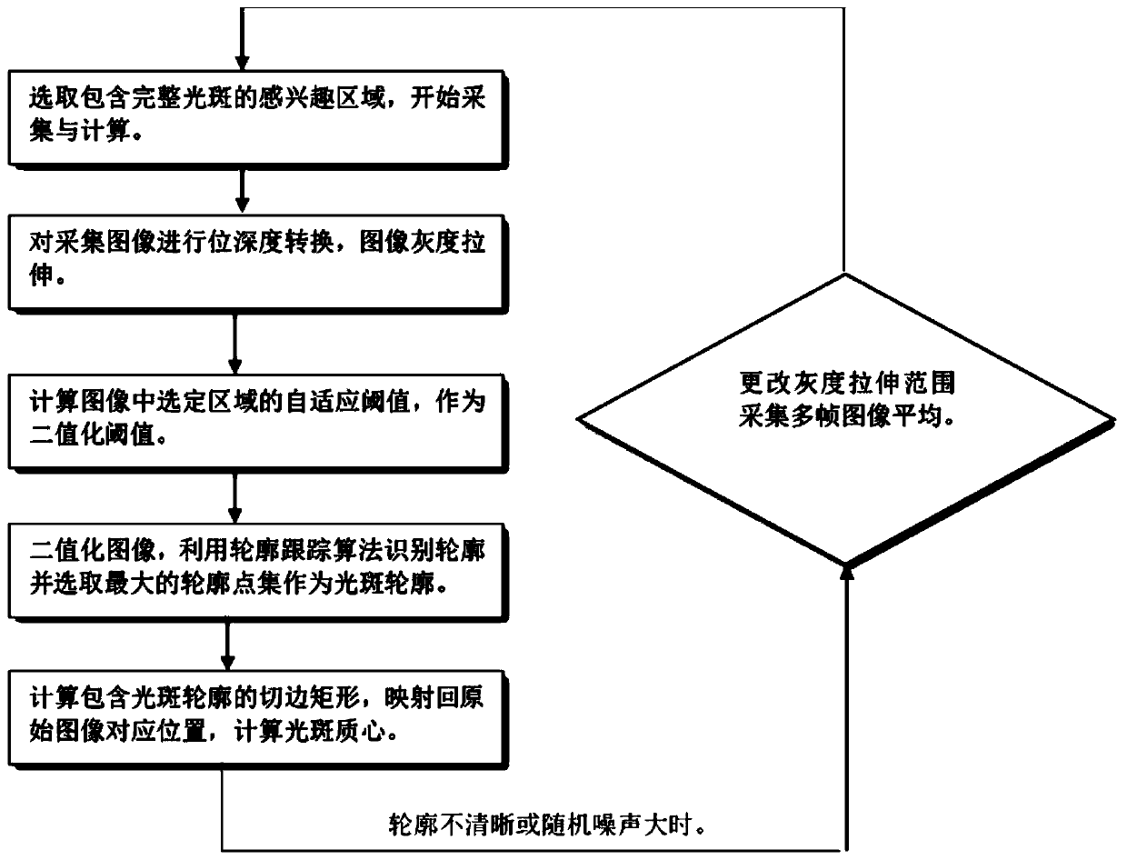
[0069] Such as figure 1 and image 3 As shown, a centroid identification and positioning method of an infrared spot image of the present invention comprises the following steps:

[0070] S1: Use the image that needs to be identified and positioned as the centroid area of ​​the infrared spot as the image of the region of interest;

[0071] S2: Perform depth conversion and grayscale linear stretching on the image of the region of interest according to the image features of the region of interest image to generate a preprocessed image;

[0072] S3: Perform adaptive threshold calculation on the pre-processed image to obtain a binarization threshold of the pre-processed image;

[0073] S4: Binarize the preprocessed image according to the binarization threshold, find out the contour according to the contour tracking algorithm, and select the largest contour point set as the spot contour;

[0074] S5: Locate the centroid of the infrared spot according to the profile of the spot. ...


PUM


Abstract

The invention discloses a centroid identification and positioning method for an infrared facula image. The method comprises the following steps: taking an image of an infrared light spot centroid areaneeding to be identified and positioned as an interested area image; performing depth conversion and gray linear stretching on the region-of-interest image to generate a preprocessed image; performing adaptive threshold calculation on the preprocessed image to obtain a binarization threshold of the preprocessed image; binarizing the preprocessed image, finding out an object contour in the regionaccording to a contour tracking algorithm, and selecting a maximum contour point set as a light spot contour; and positioning the mass center of the infrared light spot according to the light spot contour. According to the centroid recognition and positioning method for the infrared light spot image, the binarization threshold obtained through the adaptive threshold method changes along with imagefeature transformation, object contour information can be better extracted, the adaptability is higher, and the anti-noise capacity is higher. And a selected contour tracking algorithm and a maximumcontour point set are selected as light spot contours, so that the light spot contours can be well determined, and the speed is higher.

Description

technical field [0001] The invention relates to the field of infrared image analysis and the field of infrared imaging equipment performance parameter testing, in particular to a method for identifying and locating the centroid of an infrared spot image. Background technique [0002] As a kind of night vision equipment and temperature distribution detection equipment, infrared imaging equipment is widely used in civil and military fields. The test requirements of its performance parameters are getting higher and higher with the development of infrared imaging technology. The high-precision spot image center of mass positioning technology can effectively improve the test accuracy, especially in the test of the off-axis degree of the installation reference, the consistency of the optical axis, and the amount of zero movement. At the same time, the application of infrared in object detection, security monitoring, etc. has higher requirements for the real-time and target detecti...

Claims


Application Information

Patent Timeline
Patent Type & Authority Applications(China)
IPC IPC(8): G06T7/66G06T7/136G06T7/194G06T7/13G06K9/32
CPCG06T7/66G06T7/136G06T7/194G06T7/13G06T2207/10048G06T2207/20004G06V10/25
Inventor 郑兴王敬辉唐稳朱萌吴景彬刘子骥赵嘉学蒋亚东
Owner UNIV OF ELECTRONICS SCI & TECH OF CHINA
Learn More