Auxiliary equipment for maintenance and installation of electric power equipment for power engineering

A technology for electrical equipment and electrical engineering, applied in switchgear, electrical components, etc., can solve problems such as low safety, damage to maintenance and installation personnel, damage to casters, etc., to increase the contact area, avoid personal injury, and smooth lifting operations.

Active Publication Date: 2020-07-28
湖南华维建设有限公司
View PDF13 Cites 5 Cited by
  • Summary
  • Abstract
  • Description
  • Claims
  • Application Information

AI Technical Summary

Problems solved by technology

[0003] A variety of auxiliary equipment is used in the maintenance and installation of power equipment used in electric power engineering. The common auxiliary equipment is to lift the maintenance installation to a designated position for maintenance and installation operations, but this type of auxiliary equipment has the following defects: 1. The lifting device used does not have the anti-falling function. When the lifting device is accidentally damaged and causes a rapid fall, it is very easy to damage the maintenance and installation personnel, and the safety is low; 2. In order to facilitate movement, most of them are installed at the bottom of the auxiliary equipment Casters, the locking device on the casters is used to limit the movement of the casters, but due to the small contact area between the casters and the placement surface, it is easy to slip when in use, the stability is poor, and the safety is low. Casters are used to bear the weight, which can easily cause damage to the casters and affect the subsequent use of auxiliary equipment. For this reason, we propose an auxiliary equipment for the maintenance and installation of electrical equipment for power engineering

Method used


Image

  • Auxiliary equipment for maintenance and installation of electric power equipment for power engineering
  • Auxiliary equipment for maintenance and installation of electric power equipment for power engineering
  • Auxiliary equipment for maintenance and installation of electric power equipment for power engineering

Examples


Embodiment Construction

[0021] The following will clearly and completely describe the technical solutions in the embodiments of the present invention with reference to the accompanying drawings in the embodiments of the present invention. Obviously, the described embodiments are only some, not all, embodiments of the present invention. Based on the embodiments of the present invention, all other embodiments obtained by persons of ordinary skill in the art without making creative efforts belong to the protection scope of the present invention.

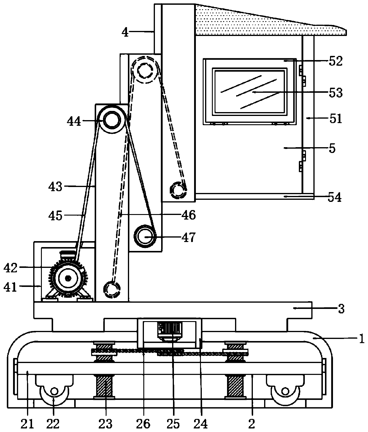
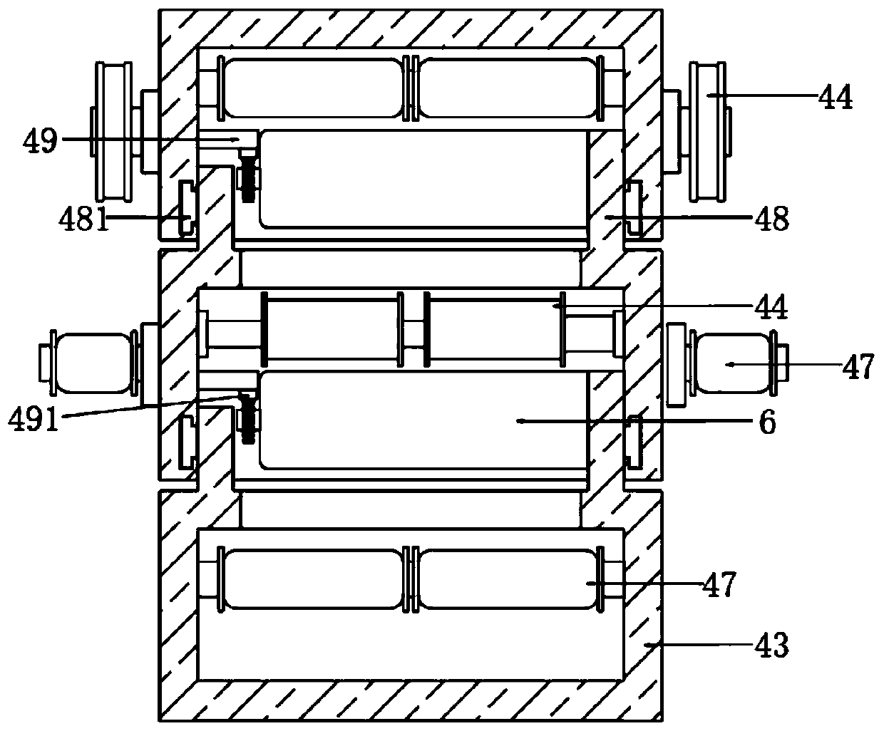
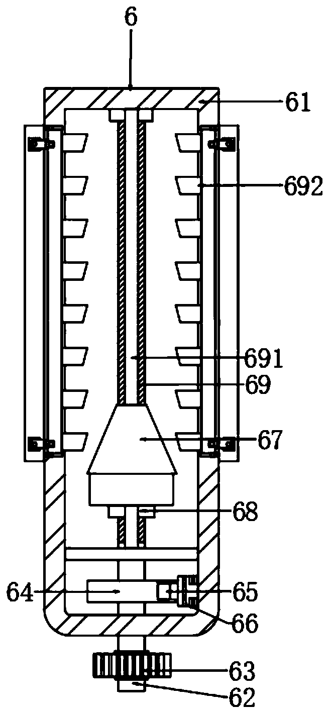
[0022] see Figure 1-4, the present invention provides a technical solution: an auxiliary equipment for maintenance and installation of electric power equipment for power engineering, please refer to figure 1 , comprising a base 1, the base 1 is provided with a placement and movement conversion mechanism 2, the placement and movement conversion mechanism 2 realizes the conversion between movement and placement, ensures the stability of placement and use, and i...


PUM


Abstract

The invention discloses auxiliary equipment for maintenance and installation of electric power equipment for electric power engineering and belongs to the technical field of the auxiliary equipment for maintenance and installation of electric power equipment. The auxiliary equipment comprises a base, wherein a placing and moving switching mechanism is arranged in the base, a top seat is fixedly arranged at the top of the base, a lifting device is fixedly arranged at the top of the top seat, and an overhaul bearing box is fixedly arranged on the right side of the lifting device. The auxiliary equipment is advantaged in that the lifting device is arranged, the occupied space is small, use cost is low, moreover, an anti-falling control mechanism is matched, when the lifting device is damaged,a middle mounting base and a right side mounting base fall down, personal injury caused by rapid fall is avoided, safety is greatly improved, during normal lifting when the rotating speed of the rotating rod is measured to be a standard speed value through cooperation of a rotating speed measuring instrument and a reflective iron patch, the driven friction block cannot interfere with the drivingfriction block, and smooth lifting operation is guaranteed.

Description

technical field [0001] The invention relates to the technical field of auxiliary equipment for maintenance and installation of power equipment, in particular to auxiliary equipment for maintenance and installation of power equipment for power engineering. Background technique [0002] Electricity is an energy powered by electric energy. It was invented in the 1870s. The invention and application of electric power set off the second industrialization climax and became one of the three scientific and technological revolutions in the world since the 18th century in human history. Since then, technology has changed people. life. The large-scale power system that appeared in the 20th century is one of the most important achievements in the history of human engineering science. It is a power production and consumption system composed of power generation, power transmission, power transformation, power distribution and power consumption. It converts the natural primary energy into...

Claims


Application Information

Patent Timeline
Patent Type & Authority Applications(China)
IPC IPC(8): H02B3/00
CPCH02B3/00
Inventor 方名亮
Owner 湖南华维建设有限公司
Why Eureka
Try Eureka