Vehicle rotor machining method

A processing method and rotor technology, applied in metal processing equipment, stator/rotor body manufacturing, tool manufacturing, etc., can solve problems such as increasing labor intensity of workers, affecting work efficiency, accidental drop and bumping, etc., to reduce clamping The process of fixing and dismantling the rotor reduces the labor intensity and the effect of reducing the occupied space

Inactive Publication Date: 2020-07-28
安徽锐锋电器有限公司
View PDF13 Cites 4 Cited by
  • Summary
  • Abstract
  • Description
  • Claims
  • Application Information

AI Technical Summary

Problems solved by technology

[0005] The purpose of the present invention is to provide a method for processing a vehicle rotor to solve the problem that when the existing vehicle rotor is polished during the processing process, manual loading of the rotor is required, and the manual participation of workers increases the labor intensity of the workers. At the same time, the rotor is manually taken, which is easy to accidentally drop and bump, resulting in damage to the rotor and resulting in waste of cost; when the existing vehicle rotor is polished during the processing process, the existing grinding and polishing equipment needs to use special fixtures Controlling the position of the rotor increases the space occupied by the overall equipment, and there is a process of clamping and fixing the rotor and disassembling the rotor, which affects the work efficiency; after the rotor is processed, the rotor needs to be manually collected and processed, which will cause human errors. Problems Affecting the Grinding and Polishing Quality of the Rotor

Method used


Image

  • Vehicle rotor machining method
  • Vehicle rotor machining method
  • Vehicle rotor machining method

Examples


Embodiment Construction

[0030] The technical solutions of the present invention will be clearly and completely described below in conjunction with the embodiments. Apparently, the described embodiments are only some of the embodiments of the present invention, not all of them. Based on the embodiments of the present invention, all other embodiments obtained by persons of ordinary skill in the art without creative efforts fall within the protection scope of the present invention.

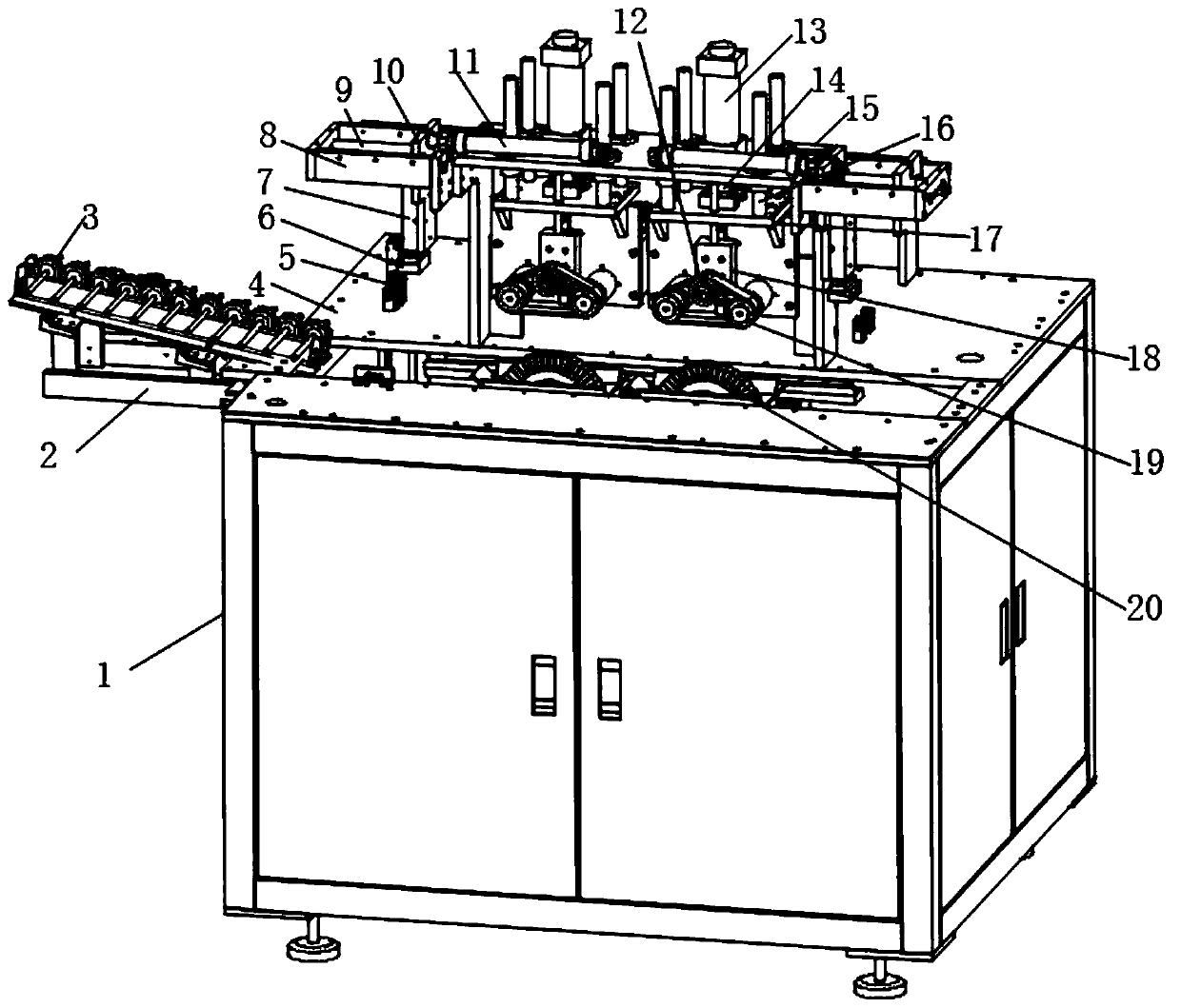
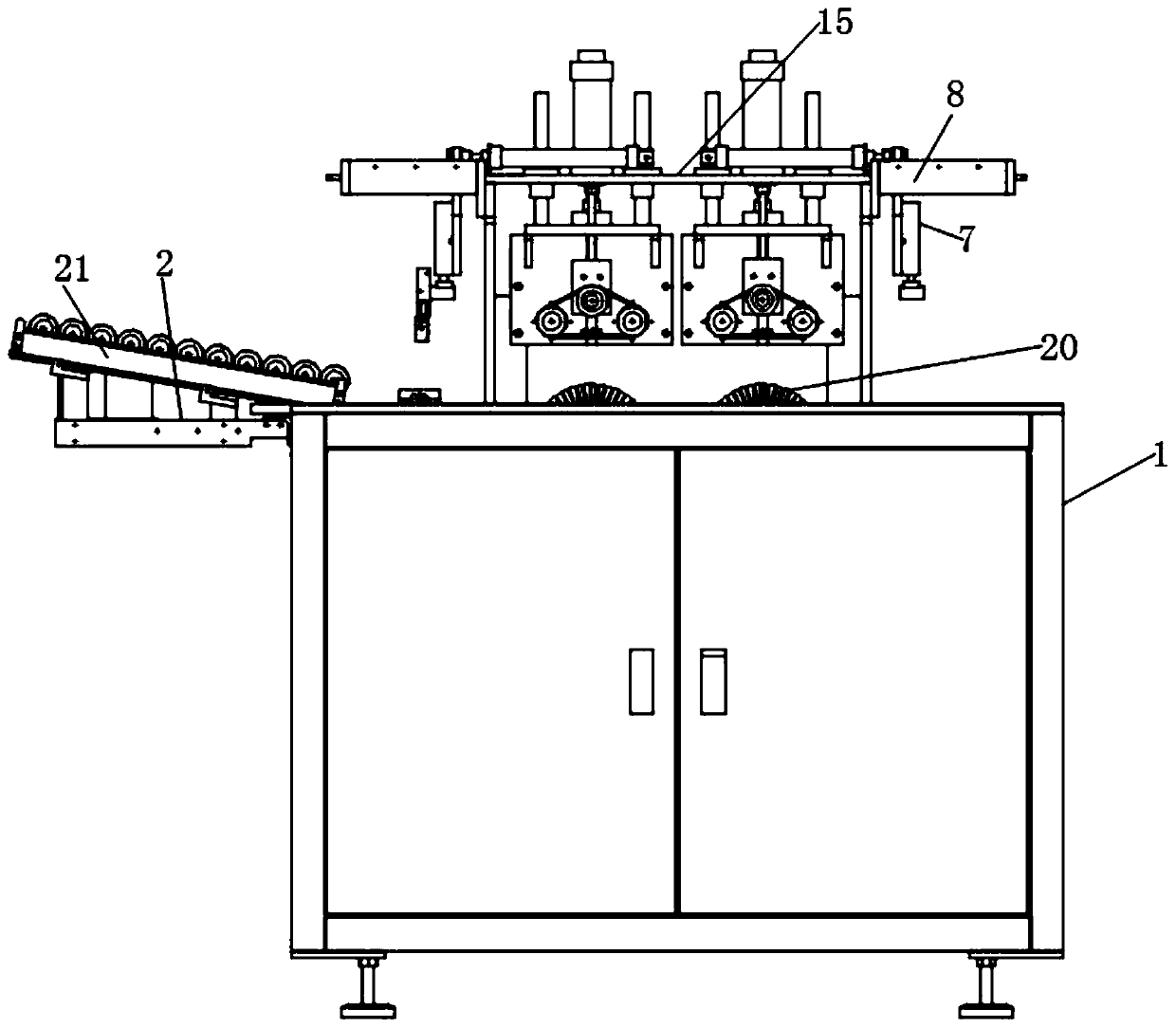
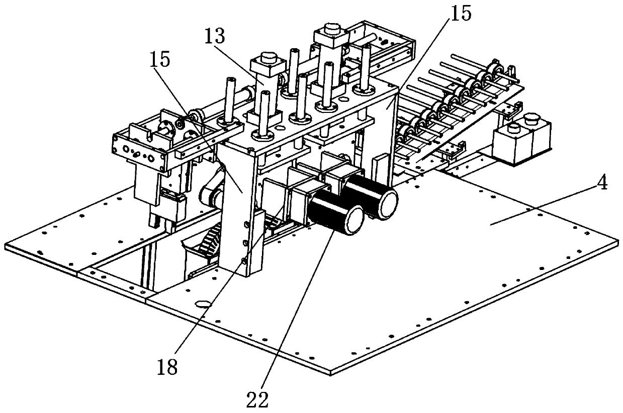
[0031] Such as Figure 1-5 As shown, a method for processing a rotor for a vehicle, the method for processing a rotor for a vehicle specifically includes the following steps:

[0032] The mandrel is finished by a lathe, the mandrel and the rotor punch are placed in the tooling, and the packaging material is placed in the processing machine. After heat treatment, the packaging material hardens, so that the mandrel and the rotor punch can be connected. Winding through the stator and rotor of the motor, welding the remaining ...


PUM


Abstract

The invention discloses a vehicle rotor machining method. The vehicle rotor machining method specifically comprises steps that finish machining of a mandrel is conducted through a lathe, the mandrel and a rotor punching sheet are placed in the tool, a packaging material is put into a processing machine, after heating treatment, the packaging material is hardened, therefore, a core shaft and the rotor punching sheet are connected together, a left wire end and a welding point of the commutator are welded together after wire winding is finished, and the like, a second piston rod in a second hydraulic cylinder is controlled to move downwards through the second hydraulic cylinder, a pressing belt is in contact with a top surface of a rotor, pressure is applied to a top surface of the rotor, therotor does not slide relative to a transmission track, an output end of the second motor drives the rotating shaft to rotate, the rotating shaft drives a grinding disc to rotate, an outer surface ofthe rotor is ground and polished, a clamp does not need to be used for controlling the position of the rotor, the occupied space of the whole equipment is reduced, the processes of clamping, fixing and detaching the rotor through the clamp are reduced, and working efficiency is improved.

Description

technical field [0001] The invention relates to the field of rotor processing equipment, in particular to a method for processing a vehicle rotor. Background technique [0002] The rotor refers to a rotating body supported by bearings. The motor in the car needs to use the rotor, and the rotor for the car needs to be polished and polished when it is processed. [0003] When the existing vehicle rotors are polished during the processing process, manual loading of the rotors is required. The manual participation of the workers increases the labor intensity of the workers. At the same time, the manual handling of the rotors is prone to accidental dropping and bumping. Cause damage to the rotor, resulting in waste of cost; when the existing vehicle rotor is polished during the processing process, the existing grinding and polishing equipment needs to use a special fixture to control the position of the rotor, which increases the space occupied by the overall equipment, and ther...

Claims


Application Information

Patent Timeline
Patent Type & Authority Applications(China)
IPC IPC(8): H02K15/02B24B5/04B24B5/35B24B41/06
CPCB24B5/04B24B5/35B24B5/355B24B41/06H02K15/02
Inventor 张亮生许杰顾昺
Owner 安徽锐锋电器有限公司
Why Eureka
Try Eureka