Stirring device for concrete cyclic production

A mixing device and concrete technology, applied in cement mixing devices, clay preparation devices, mixing operation control devices, etc., can solve the problems of waste of concrete raw materials, affecting the use efficiency, waste of water resources, etc., so as to reduce resource waves and improve utilization rate. , the effect of convenient discharge

Pending Publication Date: 2020-07-31
张永辉
View PDF8 Cites 6 Cited by
  • Summary
  • Abstract
  • Description
  • Claims
  • Application Information

AI Technical Summary

Problems solved by technology

[0003] The mixing device for concrete production is a kind of mechanical equipment that continuously mixes cement, sand aggregate and water (may contain admixtures and admixtures) to make concrete mixture. It is mainly composed of a mixing drum, a feeding mechanism and a discharging mechanism. Mechanism composition, which has been widely used in the field of concrete preparation, the existing mixing device for concrete production found in use, it will waste more concrete raw materials in the process of preparing concrete, because the concrete raw materials and When mixed with water, when it reaches a certain hardness, it is not convenient to put it directly into the mixing drum for reuse, which leads to its lack of recycling function, which causes waste of concrete raw materials to a certain extent, and the mixing drum needs to be cleaned regularly after a long time of use. Cleaning, the water used in the cleaning process is directly discharged to the outside, which also causes a waste of water resources. Moreover, the concrete prepared by the existing mixing device for concrete production is not easy to discharge, which affects the use efficiency. Therefore, a concrete Stirring device for cycle production

Method used


Image

  • Stirring device for concrete cyclic production
  • Stirring device for concrete cyclic production
  • Stirring device for concrete cyclic production

Examples


Embodiment

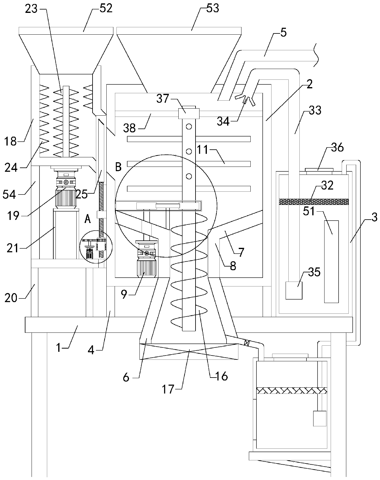
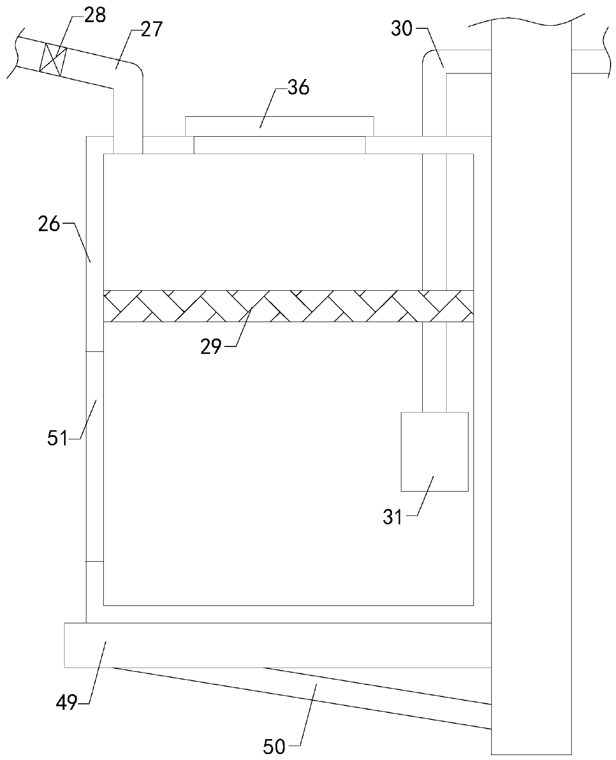
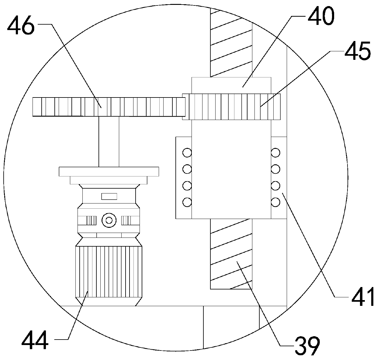
[0031] see Figure 1-6 , a mixing device for concrete circulation production, including a support frame 1, a mixing drum 2 and a water storage tank 3, the four corners of the bottom end of the mixing drum 2 are longitudinally connected with legs 4, and the bottom ends of the four legs 4 They are respectively connected to the four corners of the top middle area of ​​the support frame 1, the top of the mixing drum 2 is provided with a water inlet pipe 5, the middle part of the support frame 1 is provided with a discharge hole that penetrates up and down, and the bottom end of the mixing drum 2 is connected A discharge hopper 6 is installed, the bottom of the discharge hopper 6 passes through the discharge hole and stretches out to the outside of the bottom of the support frame 1, the outer wall of the discharge hopper 6 is fixedly connected with the inner wall of the discharge hole, and the inside of the mixing drum 2 is set There is a funnel 7, the peripheral outer wall of the ...


PUM


Abstract

The invention relates to the technical field of concrete preparation, in particular to a stirring device for concrete cyclic production. The stirring device can recycle much concrete raw material andused waste water after cleaning, reduce resource waste, facilitate outward discharge of prepared concrete, improve the use efficiency and improve the practicability. The device comprises a supportingframe, a stirring barrel and a water storage tank, wherein supporting legs are longitudinally connected to the four corners of the bottom end of the stirring barrel correspondingly, the bottom ends ofthe four supporting legs are connected with the four corners of the middle area of the top end of the supporting frame correspondingly, a water inlet pipe is arranged at the top end of the stirring barrel, a discharging hole penetrating up and down is formed in the middle of the supporting frame, a discharging hopper is installed at the bottom end of the stirring barrel in a communicating mode, the bottom end of the discharging hopper penetrates through the discharging hole and extends out to the outside of the bottom end of the supporting frame, the outer wall of the discharging hopper is fixedly connected with the inner wall of the discharging hole, a funnel is arranged in the stirring barrel, and the circumferential outer wall of the funnel is fixedly connected with the lower side areaof the circumferential inner wall of the stirring barrel.

Description

technical field [0001] The invention relates to the technical field of concrete preparation, in particular to a stirring device for concrete circulation production. Background technique [0002] As we all know, concrete, referred to as "concrete (tóng)": refers to the collective name of engineering composite materials that aggregate aggregates into a whole by cementitious materials. Generally speaking, the term concrete refers to the cement concrete obtained by mixing cement as cementing material, sand and stone as aggregate and water (may contain admixtures and admixtures) in a certain proportion, also known as ordinary concrete. , which is widely used in civil engineering. [0003] The mixing device for concrete production is a kind of mechanical equipment that continuously mixes cement, sand aggregate and water (may contain admixtures and admixtures) to make concrete mixture. It is mainly composed of a mixing drum, a feeding mechanism and a discharging mechanism. Mechan...

Claims


Application Information

Patent Timeline
Patent Type & Authority Applications(China)
IPC IPC(8): B28C5/16B28C5/08B28C7/00B28C7/16B02C4/10B02C4/28B02C4/30B08B9/093B01D29/01B01D29/56
CPCB01D29/01B01D29/56B02C4/10B02C4/28B02C4/30B08B9/093B28C5/0806B28C5/0831B28C5/16B28C7/0007B28C7/167
Inventor 张永辉
Owner 张永辉
Why Eureka
Try Eureka