Sludge treatment system and pumping device thereof

A sludge treatment and suction device technology, applied in dehydration/drying/concentrated sludge treatment, mechanically driven excavators/dredgers, earth movers/shovels, etc., can solve the inconvenient treatment of sludge and increase transportation The burden and other problems to achieve the effect of reducing turbidity and increasing structure

Inactive Publication Date: 2020-07-31
BEIJING NO 2 MUNICIPAL CONSTR ENG LTD
View PDF8 Cites 0 Cited by
  • Summary
  • Abstract
  • Description
  • Claims
  • Application Information

AI Technical Summary

Problems solved by technology

[0004] The above-mentioned existing technical solutions have the following defects: because the silt is taken out from the bottom of the river, it usually contains more water, and the r...

Method used


Image

  • Sludge treatment system and pumping device thereof
  • Sludge treatment system and pumping device thereof
  • Sludge treatment system and pumping device thereof

Examples


Embodiment Construction

[0036] The present invention will be described in further detail below in conjunction with the accompanying drawings.

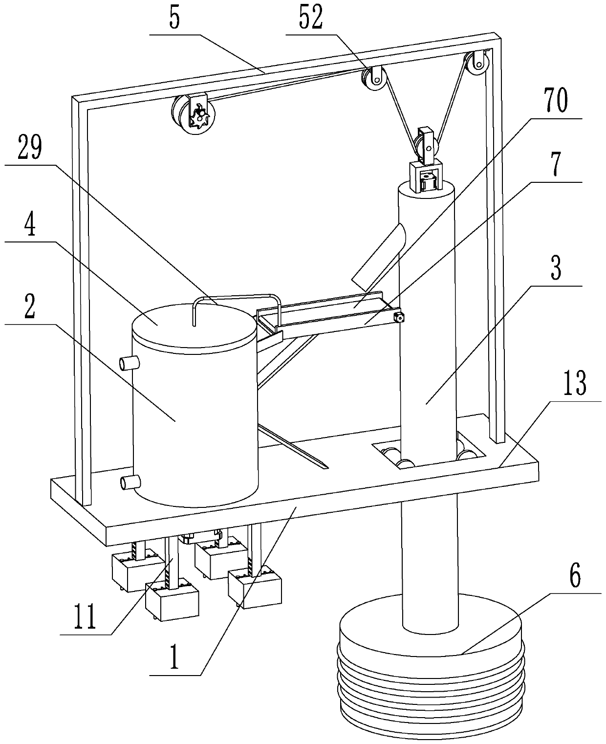
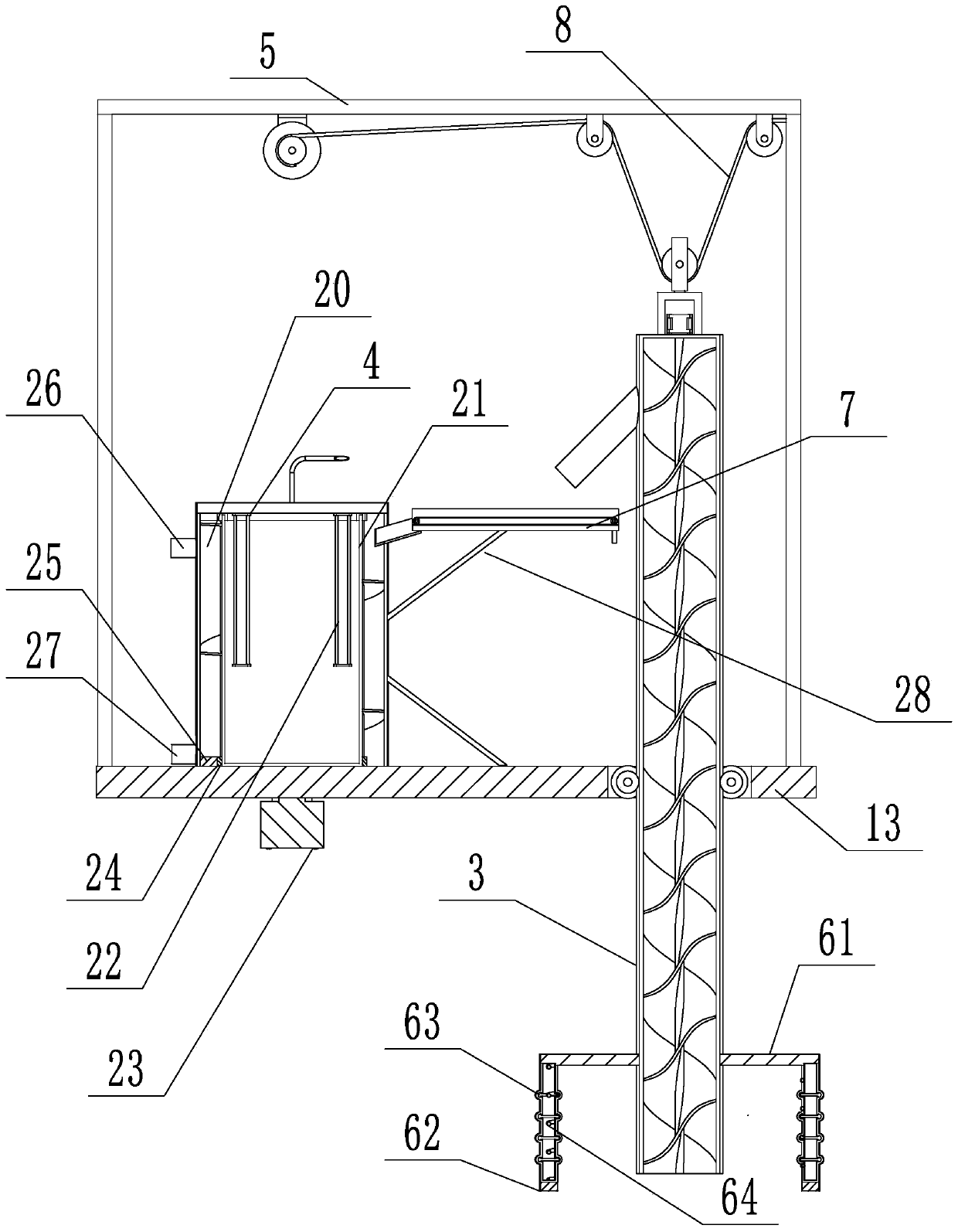
[0037] refer to figure 1 , figure 2 , is a sludge treatment system disclosed in the present invention, comprising a base 1 and a casing 2, the base 1 is connected with a suction device, the casing 2 is formed with a cavity 20 inside, and a heating cylinder 21 is rotatably installed in the cavity 20.

[0038] refer to figure 1 , figure 2 , Helical stirring blades are formed on the outside of the heating cylinder 21, a top cover 4 is installed on the top of the shell 2, a heating tube 22 is arranged on the bottom of the top cover 4 and the heating tube 22 extends into the heating cylinder 21, and the top cover 4 and the heating cylinder 21 rotate Connected, the bottom of the base 1 is provided with a driving mechanism for driving the heating cylinder 21 to rotate. The top of the cavity 20 is provided with an exhaust pipe 26 communicating with the outside,...


PUM


Abstract

The invention relates to a sludge treatment system. The sludge treatment system comprises a base and a shell, wherein the base is connected with a suction device; a cavity is formed in the shell; a heating barrel is rotatably mounted in the cavity; spiral stirring blades are formed on the outer part of the heating barrel; a top cover is arranged on the top of the shell; a heating tube is arrangedon the bottom of the top cover and extends into the heating barrel; the top cover is rotatably connected with the heating barrel; a driving mechanism for driving the heating barrel to rotate is arranged on the bottom of the base; an exhaust tube which communicates with the outside is arranged on the top of the cavity; a discharge hole is formed in the bottom of the cavity; a conveying rack is arranged on the shell; and a conveyor belt is arranged on the conveying rack. The sludge treatment system has the effect of primarily drying pumped sludge.

Description

technical field [0001] The invention relates to the technical field of river treatment, in particular to a sludge treatment system and a suction device used therein. Background technique [0002] At present, river courses are an important part of the ecological environment and play an important role in the ecological environment and people's daily life. However, due to the gentle flow of the river in the river, silt will accumulate on the bottom of the river after a period of time. If it is not cleared for a long time, it will cause channel blockage, river water rise and water quality to deteriorate. Therefore, it is necessary to clean the river regularly. Silt treatment. [0003] Existing technologies such as the automatic desilting device provided by the patent application document with the publication number CN205502109U include a silt collection tank, a silt dredging pipe, a suction device, a winding device for winding the silt dredging pipe, and a floating frame floati...

Claims


Application Information

Patent Timeline
IPC IPC(8): E02F5/28E02F3/06E02F7/00E02F7/02E02F9/08C02F11/13
CPCC02F11/13E02F3/06E02F5/28E02F5/282E02F7/00E02F7/005E02F7/02E02F9/085
Inventor 逯平陈永华赵昕胡海波段志明高冠军兰野
Owner BEIJING NO 2 MUNICIPAL CONSTR ENG LTD
Why Eureka
Try Eureka