
Champagne tower type multi-stage throttling control valve
A technology of throttling control valves and champagne towers, which is applied in the direction of valve lifts, valve details, valve devices, etc., can solve the problems of valve failure, difficult processing, and many bending times, and achieve good anti-vibration performance, processing difficulty and Low cost, leading to robust effects
- Summary
- Abstract
- Description
- Claims
- Application Information
AI Technical Summary
Problems solved by technology
Method used
Image

Examples
Embodiment Construction
[0038] For ease of understanding, the specific structure and working method of the present invention are further described as follows:
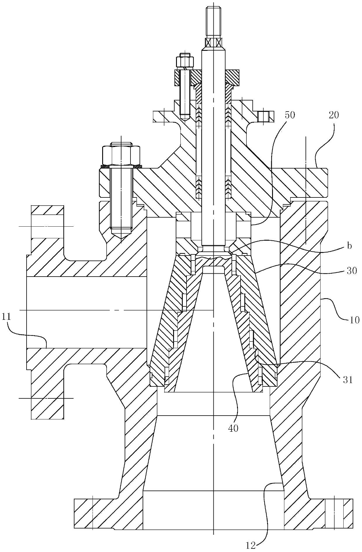
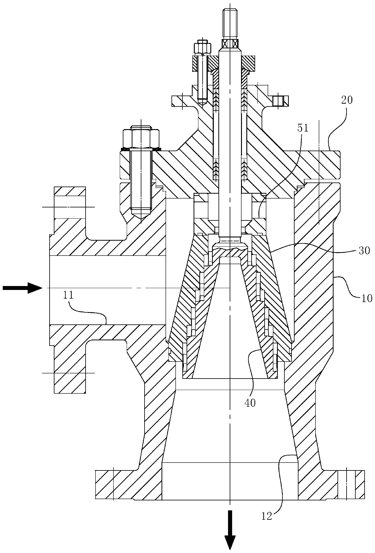
[0039] The concrete implementation structure of the present invention can refer to Figure 1-7 As shown, its main structure includes a valve body 10, a valve cover 20, a valve core 40, a throttle sleeve 30, a valve seat 50, a valve stem 60 and the like. The valve body 10 in the embodiment is an angle structure, the fluid inlet 11 is arranged through the side, and the fluid outlet 12 is arranged through the bottom. The fluid outlet 12 is provided with an expanding section or the fluid outlet 12 has a self-expanding structure. For details, refer to Figure 1-2 shown.
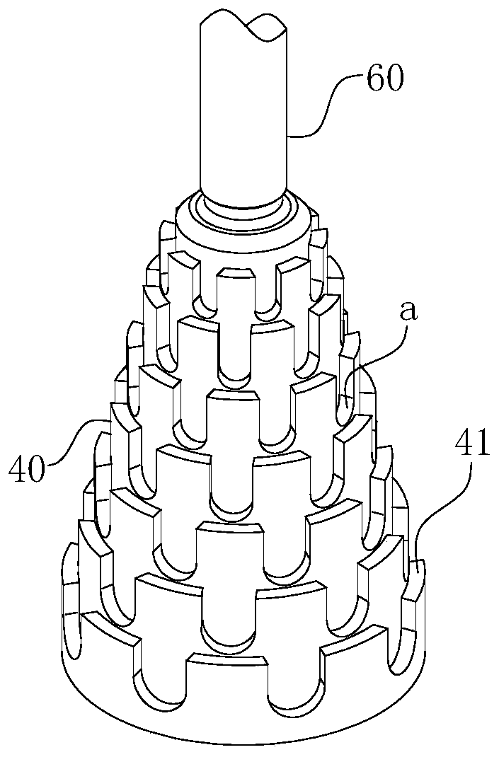
[0040] For the spool 40 and the throttling sleeve 30, as shown in the figure Figure 1-7 As shown, both are stepped, and the shaft diameter, aperture and length match each other. In other words, in Figure 1-2 In the structure shown, the spool 40 is a multi-layer stepped shaf...
PUM
 Abstract
Description
Claims
Application Information