Eureka AIR delivers breakthrough ideas for toughest innovation challenges, trusted by R&D personnel around the world.

Pedal travel data compensation method in brake test

A pedal stroke and data compensation technology, which is applied in the direction of measuring devices, complex mathematical operations, instruments, etc., can solve problems such as the deviation of the measurement results of the pull-wire pedal stroke sensor, and achieve the effect of low cost, no investment cost, and guaranteed accuracy

Inactive Publication Date: 2020-07-31
FAW CAR CO LTD
View PDF5 Cites 0 Cited by
  • Summary
  • Abstract
  • Description
  • Claims
  • Application Information

AI Technical Summary

Problems solved by technology

[0004] The purpose of the invention is to solve the problem that there is a deviation in the measurement results of the cable-type pedal travel sensor

Method used


Image

  • Pedal travel data compensation method in brake test
  • Pedal travel data compensation method in brake test
  • Pedal travel data compensation method in brake test

Examples


Embodiment Construction

[0020] In this embodiment, a method for compensating pedal stroke data in a brake test, the specific steps are as follows:

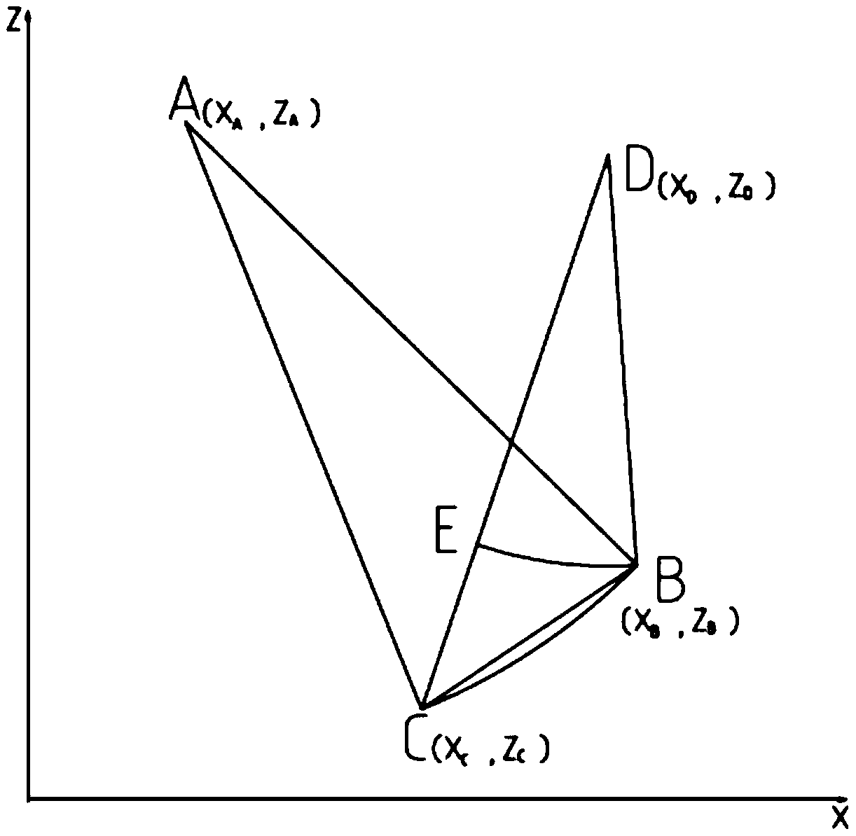
[0021] 1) Determine the relative position of the pedal and the sensor according to the modeling results of the CATIA software, convert the pedal rotation axis and load point, and the output point of the sensor cable to a two-dimensional plane (usually a vertical plane) to establish a rectangular coordinate system, and the origin of the coordinate system can be according to Modeling result selection of suitable location, where point A(X A ,Z A ) is the pedal rotation axis, point B (X B ,Z B ) is the initial position of the pedal load point, point C (X C ,Z C ) is the position of the load point at a certain moment in the braking process, point D(X D ,Z D ) is the output point of the sensor cable, and the coordinates of A, B, and D are known.

[0022] 2) Take point B as the initial point, point D as the center of the circle, and line segment BD as th...


PUM


Abstract

The invention discloses a pedal travel data compensation method in a brake test, and the method comprises the steps: a measurement result of a stay wire type travel sensor and the actual displacementof a pedal forming a geometric figure, processing the figure through a mathematic calculation method, and obtaining the actual value of the displacement of the pedal; performing variable setting on ameasured value and an actual value to form a function relational expression of the measured value and actual displacement, performing formula editing through common office software or mathematical software, and achieving rapid batch processing. The advantages of simplicity, convenience and low cost of the stay wire type stroke sensor are ensured, and the accuracy of a measurement result is also ensured.

Description

technical field [0001] The invention relates to a data processing method of a pedal stroke in a brake test. Background technique [0002] At present, the detection of the pedal stroke in the existing brake test is performed by a pedal robot or a wire-drawn stroke sensor. Pedal robots are accurate in measurement, but they have disadvantages such as high price, complicated installation, and inconvenient driving operation for the driver; cable-type travel sensors are low in cost, simple in structure, easy to install, and do not hinder driving operations, but their structure and fixing method may cause the measurement results to differ from There is actually a deviation. [0003] The measurement deviation of the cable-type pedal travel sensor is as follows: convert the brake pedal rotation axis and load point, and the output point of the sensor cable to a two-dimensional plane to form a geometric figure, as shown in the attached figure 1 shown. Point A is the rotation axis of...

Claims


Application Information

Patent Timeline
IPC IPC(8): G01B21/04G06F17/12
CPCG01B21/04G06F17/12
Inventor 金平何晓引王雷刘相斌姚诚魏国凯刘万喜张华文张秀
Owner FAW CAR CO LTD
Why Eureka
Eureka Blog
Learn More