Piezoelectric sensor based on vehicle dynamic weighing array

A piezoelectric sensor and pressure sensor technology, which is applied to the detailed information of weighing equipment, instruments, measuring devices, etc., can solve the problems of stones entering, affecting the service life of piezoelectric sensors, and affecting the normal use of piezoelectric sensors in foundation pits, etc. , to improve the accuracy of the

Active Publication Date: 2020-07-31
费波斯测量技术(常州)有限公司
View PDF7 Cites 6 Cited by
  • Summary
  • Abstract
  • Description
  • Claims
  • Application Information

AI Technical Summary

Problems solved by technology

The disadvantage is that some piezoelectric materials need moisture-proof measures, and the output DC response is poor, and high input impedance circuits or charge amplifiers need to be used to overcome this defect
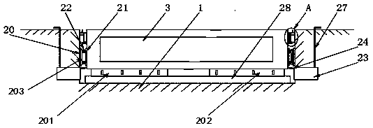
[0003] When weighing vehicles on the expressway, piezoelectric sensors are generally used for weighing. Generally, a foundation pit is dug on the ground, and a weighing device with a piezoelectric sensor is installed in the foundation pit for weighing. The prior art In the middle, due to the large gap between the weighing plate and the foundation pit on the ground, when it is used for a long time, a large number of stones will enter these large gaps, and it will accumulate over the years, which will affect the piezoelectric sensor inside the foundation pit. Normal use, and there is easy rainwater accumulation inside the foundation pit, which affects the service life of the piezoelectric sensor

Method used


Image

  • Piezoelectric sensor based on vehicle dynamic weighing array
  • Piezoelectric sensor based on vehicle dynamic weighing array
  • Piezoelectric sensor based on vehicle dynamic weighing array

Examples


Embodiment Construction

[0037] In the following description, numerous specific details are given in order to provide a more thorough understanding of the present invention. It will be apparent, however, to one skilled in the art that embodiments of the invention may be practiced without one or more of these details. In other examples, some technical features known in the art are not described in order to avoid confusion with the embodiments of the present invention.

[0038] In order to thoroughly understand the embodiments of the present invention, a detailed structure will be set forth in the following description. It is evident that practice of the embodiments of the invention is not limited to specific details familiar to those skilled in the art. Preferred embodiments of the present invention are described in detail below, however, the present invention may have other embodiments besides these detailed descriptions.

[0039] In the description of the present invention, the orientation or posit...


PUM


Abstract

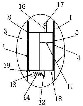
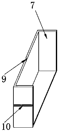
The invention discloses a piezoelectric sensor based on a vehicle dynamic weighing array. The piezoelectric sensor comprises a weighing unit, a sensing unit and a remote control unit, wherein the sensing unit comprises a first piezoelectric sensor group, a second piezoelectric sensor group and a transverse pressure sensor group, the weighing unit comprises a foundation pit and a weighing plate, the bottoms of the first piezoelectric sensor group and the second piezoelectric sensor group are fixedly connected with the top of a stabilizing plate, the transverse pressure sensor group comprises afirst pressure sensor positioned on a first mounting plate on the left side of the foundation pit and a second pressure sensor positioned on a first mounting plate on the right side of the foundationpit, the remote control unit receives an electric signal of the first piezoelectric sensor group or the second piezoelectric sensor group as a measurement result value according to a preset first intermediate variable value, and the remote control unit receives an electric signal of the light pressure measuring sensor and / or the heavy pressure measuring sensor as a measurement result value according to a preset second intermediate variable value.

Description

technical field [0001] The present invention relates generally to the field of highway weighing, and more particularly to a piezoelectric sensor based on a vehicle dynamic weighing array. Background technique [0002] A piezoelectric sensor is a sensor based on the piezoelectric effect, a self-generating and electromechanical conversion sensor. Its sensitive element is made of piezoelectric material. When a piezoelectric material is subjected to a force, an electric charge is generated on its surface. After the charge is amplified by the charge amplifier and the measuring circuit and the impedance is transformed, it becomes an electric output proportional to the received external force. Piezoelectric sensors are used to measure force and non-electrical quantities that can be converted into electricity. Its advantages are wide frequency band, high sensitivity, high signal-to-noise ratio, simple structure, reliable operation and light weight. The disadvantage is that som...

Claims


Application Information

Patent Timeline
Patent Type & Authority Applications(China)
IPC IPC(8): G01G3/13G01G19/03G01G21/10G01G23/00
CPCG01G3/13G01G19/035G01G21/10G01G23/00
Inventor 李嘉宝
Owner 费波斯测量技术(常州)有限公司
Why Eureka
Try Eureka