Capacitive coupling structure of dielectric waveguide filter

A dielectric waveguide and capacitive coupling technology, applied in the field of filters, can solve problems such as easy deformation of negative coupling holes, and achieve the effects of improving design flexibility, improving squareness, and improving suppression characteristics

Inactive Publication Date: 2020-07-31
安徽浩源恒方通信技术有限公司
View PDF6 Cites 2 Cited by
  • Summary
  • Abstract
  • Description
  • Claims
  • Application Information

AI Technical Summary

Problems solved by technology

[0004] The technical problem to be solved by the present invention is to provide a capacitive coupling structure of a dielectric waveguide filter for the deficiencies of the prior art, which solves the problems caused by the negative coupling hole being too deep The problem of easy deformation after sintering

Method used


Image

  • Capacitive coupling structure of dielectric waveguide filter
  • Capacitive coupling structure of dielectric waveguide filter
  • Capacitive coupling structure of dielectric waveguide filter

Examples


Embodiment Construction

[0016] Below in conjunction with embodiment, the present invention is further described, but does not constitute any restriction to the present invention, anyone makes the limited number of amendments in the scope of claims of the present invention, still within the scope of claims of the present invention.

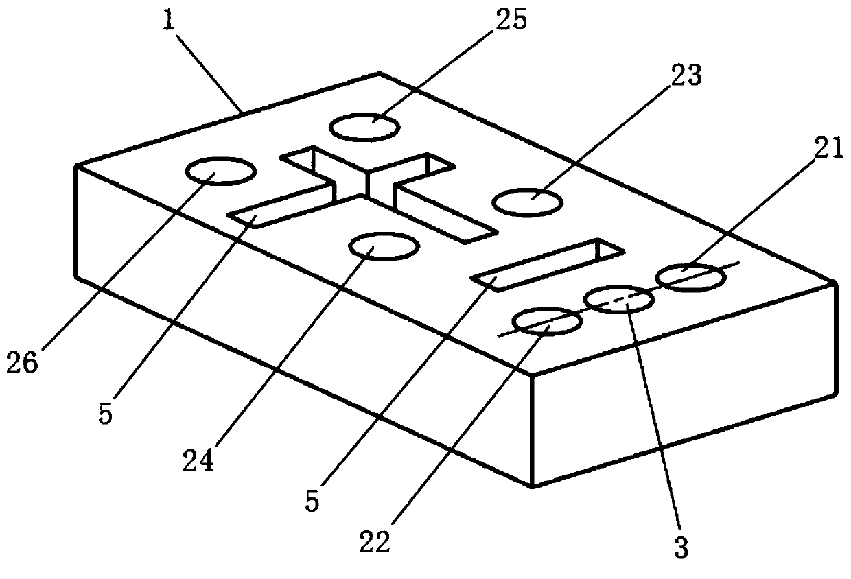
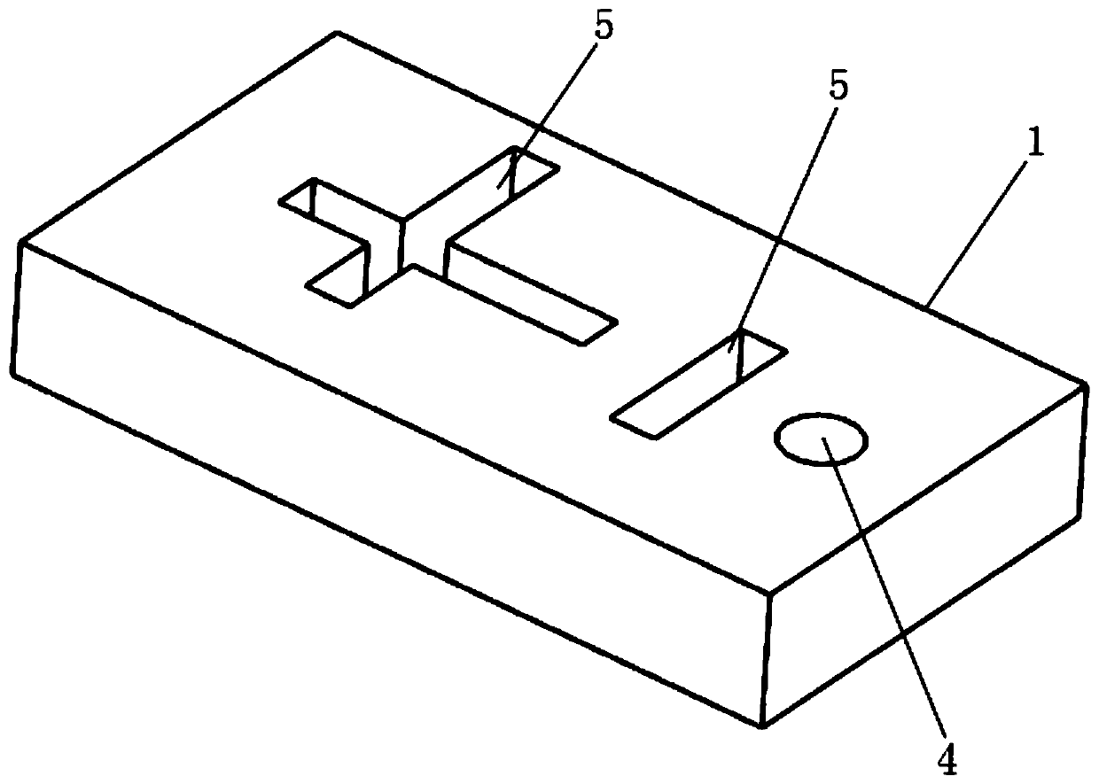
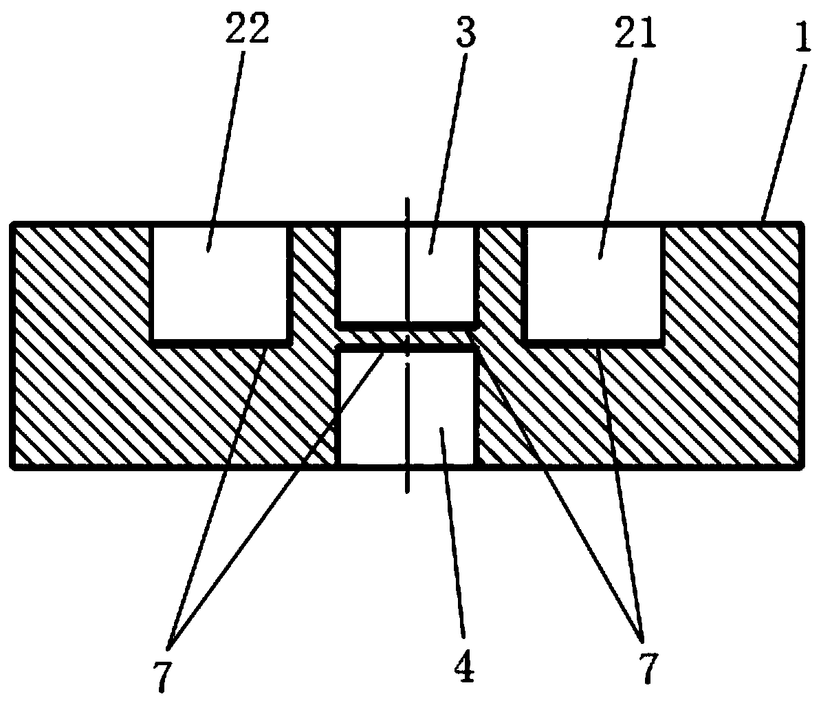
[0017] In the capacitive coupling structure of a dielectric waveguide filter of the present invention, the capacitive coupling structure is arranged at the midpoint of the connection line between the debugging holes 2 of two adjacent resonators. The dielectric waveguide filter body 1 of this embodiment is a solid solid dielectric powder, and the solid dielectric powder is ceramic. The dielectric waveguide filter body 1 is rectangular. Dielectric waveguide filter body 1 is provided with six resonators. The resonators are separated by through slots 5 , and each resonator is provided with a debugging hole 2 . That is, the dielectric waveguide filter body 1 is provided with...


PUM


Abstract

The invention discloses a capacitive coupling structure of a dielectric waveguide filter, relates to the field of filters, and solves the technical problem that a negative coupling hole is easy to deform after being sintered due to the fact that the negative coupling hole is too deep. The capacitive coupling structure is arranged at the midpoint of the connecting line of the debugging holes of twoadjacent resonators; the capacitive coupling structure comprises a first blind hole located in the upper surface of the dielectric waveguide filter body and a second blind hole located in the lower surface of the dielectric waveguide filter body, and the first blind hole and the second blind hole form a negative coupling hole; the sum of the depths of the first blind hole and the second blind hole is larger than the depth of the debugging hole and smaller than the distance between the upper surface and the lower surface of the dielectric waveguide filter body; and the first blind hole and thesecond blind hole are coaxially arranged. According to the invention, the rectangular coefficient, the suppression characteristic and the design flexibility of the filter are improved; and the negative coupling holes of the up-and-down symmetrical structure can enable the powder to have better fluidity during dry pressing, the density of each part of the dielectric waveguide filter body is uniform, and the problem that the negative coupling holes are easy to deform in the sintering process is avoided.

Description

technical field [0001] The present invention relates to filters, more specifically, it relates to a capacitive coupling structure of a dielectric waveguide filter. Background technique [0002] In the field of mobile communication, with the development of technology, the requirements for the frequency selection performance and miniaturization of the filter in the system are continuously improved. The dielectric waveguide filter realized by the new high dielectric constant powder can meet the requirements of high performance, miniaturization and low cost. Require. [0003] According to the out-of-band frequency selection requirements of the high-power microwave filter at the base station of the mobile communication system, it is generally necessary to add a transmission zero point when designing the filter. However, due to the limited powder material and structure of the dielectric filter, it is more difficult to achieve capacitive cross-coupling than the metal filter. Pate...

Claims


Application Information

Patent Timeline
Patent Type & Authority Applications(China)
IPC IPC(8): H01P1/20
CPCH01P1/2002
Inventor 秦佰坤
Owner 安徽浩源恒方通信技术有限公司
Why Eureka
Try Eureka