
Three-stage condensation system of VOCs purification treatment device

A purification treatment and condensation system technology, applied in gas treatment, steam condensation, multi-effect/separation condensation, etc., can solve environmental pollution and other problems, and achieve the effect of improving quality and increasing area

Pending Publication Date: 2020-08-04
内蒙古环保投资集团有限公司 +1
View PDF5 Cites 1 Cited by
  • Summary
  • Abstract
  • Description
  • Claims
  • Application Information

AI Technical Summary

Problems solved by technology

[0005] The current market is still blank in the treatment of organic waste gas (VOCs), and there is no suitable method or equipment. Organic waste gas will still be discharged into the atmosphere and pollute the environment.

Method used


Image

  • Three-stage condensation system of VOCs purification treatment device
  • Three-stage condensation system of VOCs purification treatment device
  • Three-stage condensation system of VOCs purification treatment device

Examples


Embodiment 1

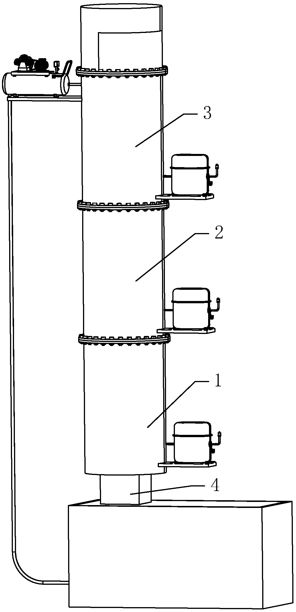
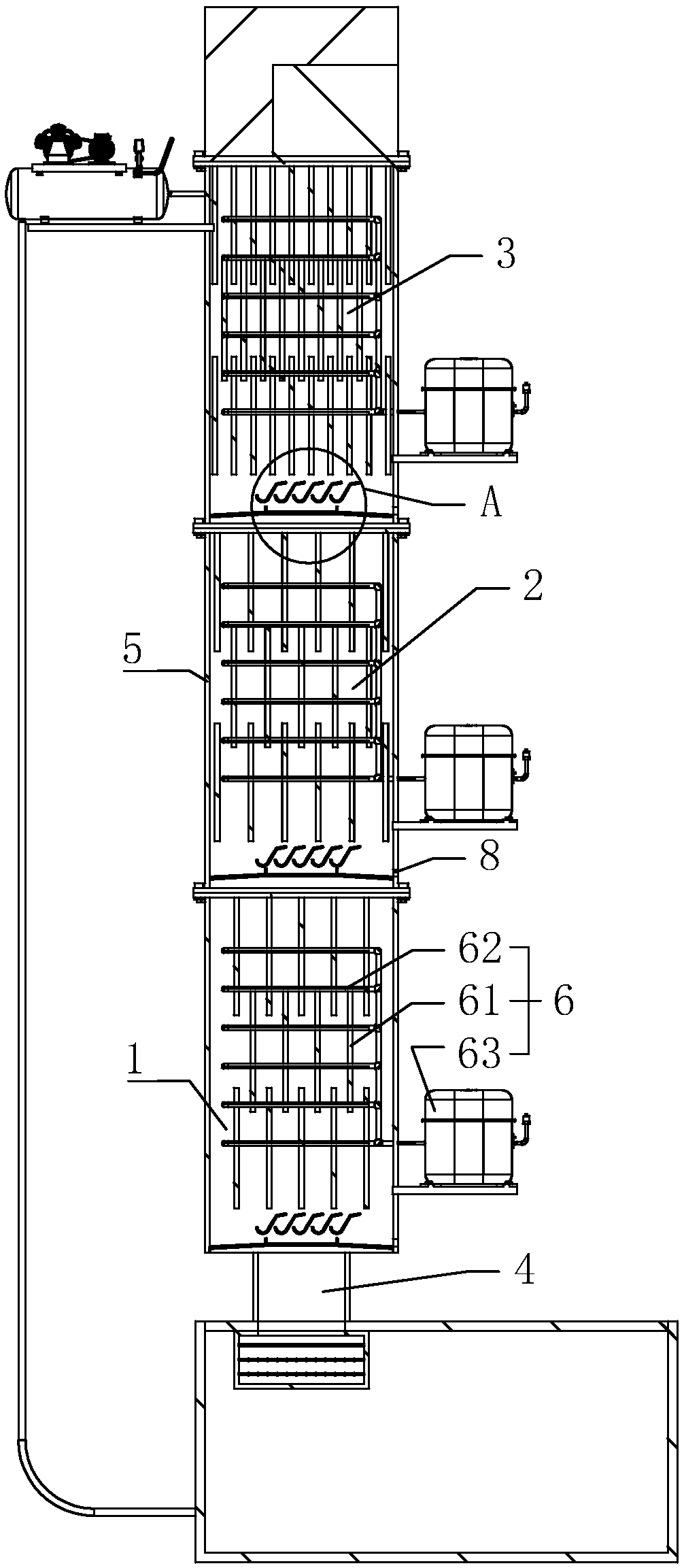
[0039] Embodiment one: a kind of three-stage condensing system of VOCs purification treatment device, such as figure 1 with 2 As shown, it includes a primary primary cooling system 1, a secondary intercooling system 2 arranged above and connected to the primary primary cooling system 1, a tertiary deep cooling system 3 arranged above and connected to the secondary intercooling system 2, and a The primary primary cooling system 1 , the secondary intercooling system 2 and the tertiary cryogenic system 3 all include a thermal insulation bucket 5 and a refrigeration assembly 6 connected to the thermal insulation bucket 5 .

[0040] Such as figure 2 As shown, the first-level primary cooling system 1, the second-level intercooling system 2 and the third-level cryogenic system 3 all include a heat preservation barrel 5 and a refrigeration assembly 6 connected to the heat preservation barrel 5. The refrigeration assembly 6 includes a Several refrigerating sheets 61 in the 5, the co...

Embodiment 2

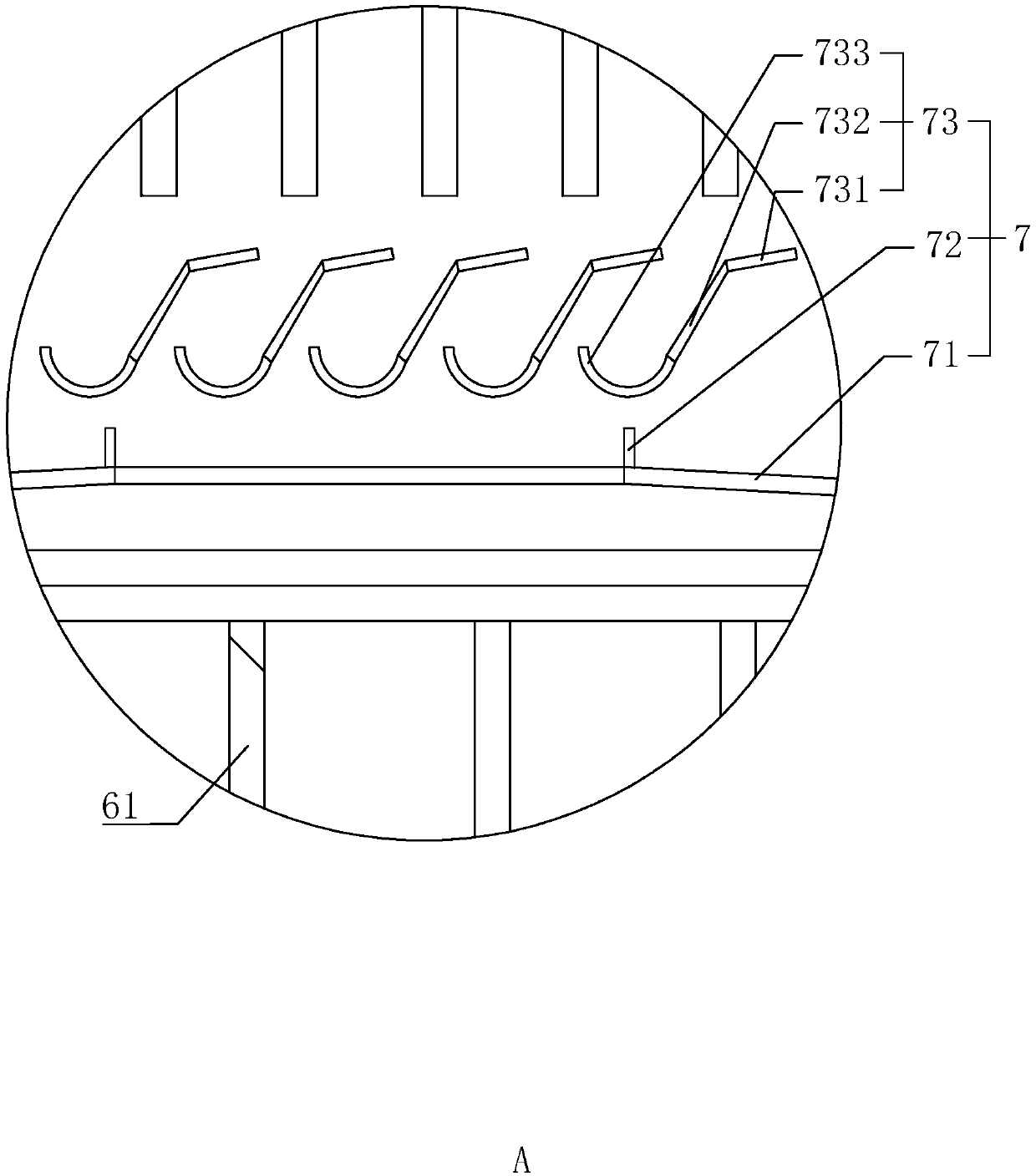
[0050] Embodiment 2: The difference from Embodiment 1 is that, as Figure 5 with 6 As shown, the non-return assembly 73 includes a non-return cap 734 arranged above the collection ring plate 71, a support rod 735 connecting the non-return cap 734 and the collection ring plate 71, the non-return cap 734 covers the opening of the collection ring plate 71, and extends The side above the collecting ring plate 71 is located on the side of the baffle plate 72 away from the center of the heat preservation bucket 5 . The condensed chemical substances fall onto the non-return cap 734, and slide down to the collection ring plate 71 along the non-return cap 734, effectively realizing that the condensed chemical substances fall into the condensing system of the lower stage, and the non-return cap 734 also does not affect the flow of non-condensable gas in VOCs to the upstream condensation system.


PUM


Abstract

The invention discloses a three-stage condensation system of a VOCs purification treatment device. The invention belongs to the field of waste gas treatment in the coking industry. The system comprises a first-stage primary cooling system, a second-stage inter-cooling system arranged above the first-stage primary cooling system and communicated with the first-stage primary cooling system, and a third-stage copious cooling system arranged above the second-stage inter-cooling system and communicated with the second-stage inter-cooling system; a diffusion opening is formed in the lower portion ofthe first-stage primary cooling system; the first-stage primary cooling system, the second-stage inter-cooling system and the third-stage copious cooling system each internally comprise a thermal insulation barrel and a refrigeration assembly connected with the thermal insulation barrel; and non-return collection structures are arranged in the first-stage primary cooling system, the second-stageinter-cooling system and the third-stage copious cooling system. Through the first-stage primary cooling system, the second-stage inter-cooling system and the third-stage copious cooling system, VOCscan be purified, and the effect of zero emission is achieved; and through the arrangement of the non-return collection structures, chemical substances in all the condensation systems can be recycled,and the effect of classified recycling is achieved.

Description

technical field [0001] The invention relates to the field of waste gas treatment in the coking industry, in particular to a three-stage condensation system of a VOCs purification treatment device. Background technique [0002] With the rapid development of the iron and steel industry, the coking industry has also made great progress, but the environmental pollution is also becoming more and more serious. As the country proposes policies such as capacity reduction and structural adjustment, environmental protection will be one of the rigid targets for the coking industry. Among the various environmental protection issues in the coking industry, the pollution of waste gas from the coking industry is particularly prominent. [0003] Coking industrial waste gas can be divided into inorganic waste gas and organic waste gas according to its chemical properties. Inorganic waste gas includes SO2, NOx, ammonia, H2S, etc.; organic waste gas (VOCs) is a general term for volatile orga...

Claims


Application Information

Patent Timeline
Patent Type & Authority Applications(China)
IPC IPC(8): B01D53/00B01D5/00
CPCB01D53/002B01D5/0036B01D2257/708
Inventor 肖志才孙乐
Owner 内蒙古环保投资集团有限公司
Learn More