An ultrafast current detection device and pulse test system

A technology for current detection and pulse testing, which is applied in the direction of measuring devices, pulse characteristic measurement, and current-only measurement, and can solve problems such as affecting current detection, inability to accurately detect current pulses, and detection system mismatch

Active Publication Date: 2022-07-01
INST OF MICROELECTRONICS CHINESE ACAD OF SCI
View PDF8 Cites 0 Cited by
  • Summary
  • Abstract
  • Description
  • Claims
  • Application Information

AI Technical Summary

Problems solved by technology

However, the above operation needs to strip the transmission line and let the core wire of the transmission line pass through the current probe, which will cause the mismatch of the detection system and affect the detection of the current
Moreover, due to the bandwidth limitation of the current probe, it cannot accurately detect the current pulse whose rising edge is less than 200ps

Method used


Image

  • An ultrafast current detection device and pulse test system
  • An ultrafast current detection device and pulse test system
  • An ultrafast current detection device and pulse test system

Examples


Embodiment 2

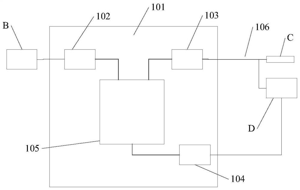
[0121] Based on the same inventive concept, the present invention also provides a pulse testing system, such as Image 6 shown, including:

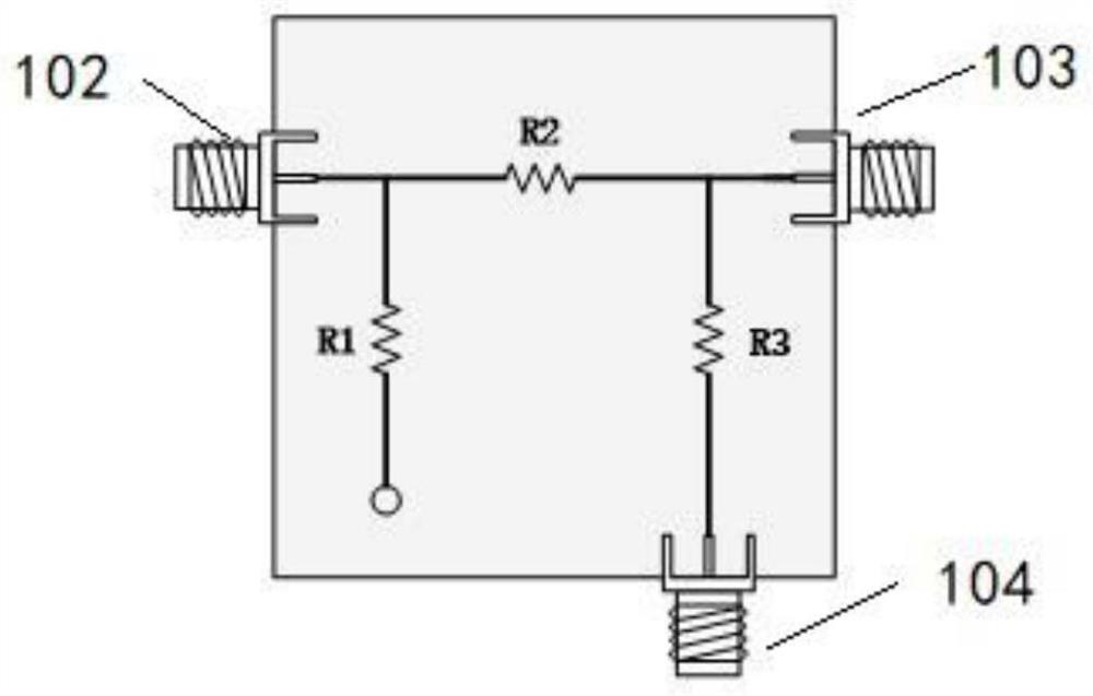
[0122] The pulse generating device B, the above-mentioned ultra-fast current detecting device (taking the impedance matching circuit of π-type structure as an example), and the detecting and receiving device D are connected in sequence.

[0123] The input coaxial connector 102 of the ultrafast current detection device is connected to the pulse generating device B, the output coaxial connector 103 of the ultrafast current detection device is connected to the device under test through the transmission line 106, and the output coaxial connector 103 is connected to the device under test through the transmission line 106. The transmission line 106 is connected to the first collection end of the detection and reception device D, and the detection coaxial connector 104 of the ultrafast current detection device is connected to the second collecti...


PUM


Abstract

The invention relates to the technical field of high-frequency current detection, in particular to an ultra-fast current detection device and a pulse test system. The device includes: an input, an output, a detection coaxial connector, and an impedance matching circuit; the impedance matching circuit includes three terminals, a third One end is connected to the pulse generating device through the input coaxial connector, the second end is connected to the device under test through the output coaxial connector through the transmission line, and the second end is connected to the first acquisition end of the detection receiving device through the output coaxial connector through the transmission line , the third end is connected to the second collection end of the detection receiving device through the detection coaxial connector, the input impedance of the impedance matching circuit and the output impedance of the impedance matching circuit, the output impedance of the pulse generating device, and the first detection and receiving device. The first impedance of a collection end and the second impedance of the second collection end are equal to the characteristic impedance of the pulse testing system, which can accurately detect the pulse signal passing through the ultrafast current detection device.

Description

technical field [0001] The invention relates to the technical field of high-frequency current detection, in particular to an ultrafast current detection device. Background technique [0002] The transmission line pulse generator (TLP) is used to measure the IV curve of the device in the process of being subjected to electrostatic pulses, and provides the required simulation parameters for the electrostatic discharge (ESD) protection global protection structure. Most ESD protection will use the transmission line pulse generator. [0003] The current detection system of the existing TLP system is often composed of an inductive current probe and an oscilloscope. Specifically, the TLP system has a transmission section transmission line. When performing current detection, the current probe is directly inserted into the core wire of the transmission line. The core wire of the transmission line is made to pass through the current probe. When the current flows through the probe, an ...

Claims


Application Information

Patent Timeline
Patent Type & Authority Patents(China)
IPC IPC(8): G01R19/00G01R29/02G01R1/30
CPCG01R19/0092G01R29/02G01R1/30
Inventor 王娟娟曾传滨倪涛孙佳星罗家俊韩郑生王玉娟张煦
Owner INST OF MICROELECTRONICS CHINESE ACAD OF SCI
Why Eureka
Try Eureka