
Multiplexing light source binocular optical display system and wearable equipment

An optical display and binocular technology, applied in the field of AR, can solve the problems of easy leakage in the display, size, price, field of view, performance, observation distance, and poor confidentiality.

Pending Publication Date: 2020-08-04
NINGBO HONGYI OPTO ELECTRONICS CO LTD
View PDF0 Cites 4 Cited by
  • Summary
  • Abstract
  • Description
  • Claims
  • Application Information

AI Technical Summary

Problems solved by technology

Among them, the geometric optics scheme is the main idea. Compared with the diffraction scheme, it has the characteristics of mature technology, convenient device processing, and small assembly tolerance requirements. It is currently favored by many manufacturers such as Google, Lenovo, and Microsoft. Limited to the overall size, weight / price requirements of the light source device and the AR system, there are common problems that the size, price, field of view, performance, and observation distance cannot be taken into account, and the displayed content is easy to leak, and the confidentiality is poor; An additional myopia lens is required to be used together with the optical system
These disadvantages reduce the experience of using augmented reality wearable devices

Method used


Image

  • Multiplexing light source binocular optical display system and wearable equipment
  • Multiplexing light source binocular optical display system and wearable equipment
  • Multiplexing light source binocular optical display system and wearable equipment

Examples


Embodiment 1

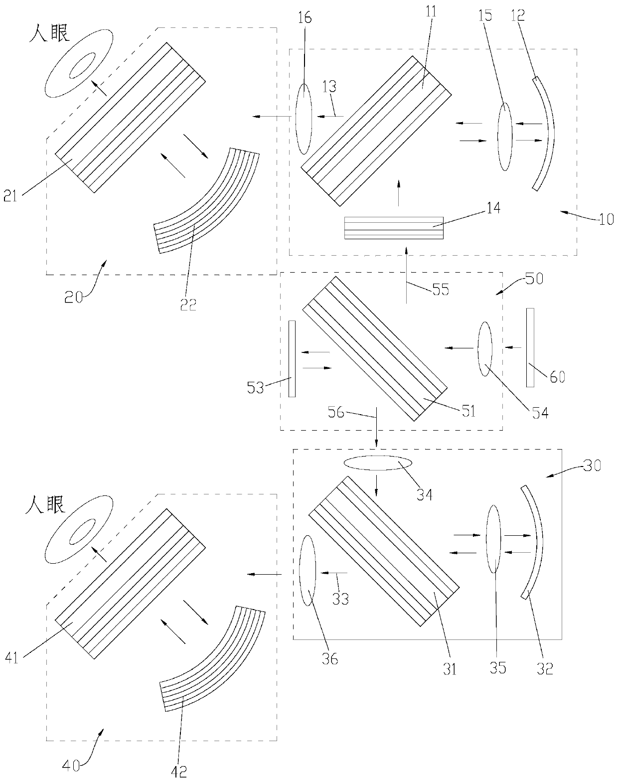
[0070] refer to figure 1 As shown, Embodiment 1 of the present invention provides a multiplexed light source binocular optical display system, including a display 60, a light splitting module 50, a first optical module 10, a second optical module 20, and a third optical module 30 and the fourth optical module 40 .

[0071] The display 60 mainly plays the role of emitting light. The display 60 can display 2D or 3D images or videos. The display 60 can be an OLED display, an LCD display, an LCOS display, a micro-LED display, a micro-OLED display or a mini-LED display, etc. , can be selected as required. In this embodiment, the display 60 is an OLED display.

[0072] The spectroscopic module 50 includes a first optical lens 51 and a second reflector 53 .

[0073] The first optical lens 51 is arranged on the light-emitting optical path of the display 60, the light of part of the display 60 is reflected from the first optical lens 51 to form the first outgoing light 55, and the li...

Embodiment 2

[0115] refer to Figure 10 As shown, Embodiment 1 of the present invention provides a multiplexed light source binocular optical display system, including a display 60, a light splitting module 50, a first optical module 10, a second optical module 20, and a third optical module 30 and the fourth optical module 40 .

[0116] It should be noted that the difference between this embodiment and the first embodiment lies in the first optical module 10 and the third optical module 30 .

[0117] The display 60, the light splitting module 50, the second optical module 20 and the fourth optical module 40 of this embodiment adopt the display 60, the light splitting module 50, the second optical module 20 and the fourth optical module in the first embodiment. For the structure, working principle and technical effects of the group 40, please refer to the corresponding content in the first embodiment, which will not be repeated here.

[0118] The first optical module 10 includes a second...

Embodiment 3

[0137] Embodiment 3 of the present invention also provides a wearable device, including a wearable component and a binocular optical display system with a multiplexed light source.

[0138] It should be noted that the multiplexed light source binocular optical display system in this embodiment can adopt the multiplexed light source binocular optical display system in Embodiment 1 or Embodiment 2, and its structure, working principle and technical effects refer to the implementation The corresponding content in Example 1 or the embodiment will not be repeated here.

[0139] The multiplex light source binocular optical display system is arranged on the wearable part. The wearing part can be a helmet or a spectacle frame, etc., so that it is convenient for people to wear it on the head. Of course, the wearable device may also include a control unit, a storage unit, etc. The control unit is convenient for controlling the device, and the storage unit is convenient for storing imag...


PUM


Abstract

The invention provides a multiplexing light source binocular optical display system and wearable equipment, and belongs to the technical field of AR. The multiplexing light source binocular optical display system comprises a display, a light splitting module, a first optical module, a second optical module, a third optical module and a fourth optical module, wherein the light splitting module is arranged on a light emitting path of the display, and processes the light incident from the display to obtain first emergent light and second emergent light; the first optical module is arranged on thelight path of the first emergent light, and the second optical module is arranged on the light path of the first optical module; and the third optical module is arranged on the light path of the second emergent light, and the fourth optical module is arranged on the light path of the third optical module. The system is small in size, good in imaging quality, free of display light leakage and goodin confidentiality. The wearable equipment is convenient to wear and good in universality, can adapt to myopic users through a compensating mirror, and greatly improves the wearing experience of theusers.

Description

technical field [0001] The invention belongs to the field of AR technology, and in particular relates to a binocular optical display system with a multiplexed light source and a wearable device. Background technique [0002] Augmented Reality (AR, Augmented Reality) is a technology that projects an image in front of the human eye through a transmission device and superimposes the real scene and the virtual scene. In this way, completely new visual experiences can be given and new fields of application can be enhanced or created. Transmissive optical display system is one of the core technologies in the field of augmented reality. At present, wearable devices using enhanced display technology have been widely used in gaming, retail, education, industry, medical and other fields. [0003] At present, the transmissive optical display technology can be divided into geometrical optics schemes: Birdbath, ordinary reflective prisms, free-form surface prisms and other schemes, and...

Claims


Application Information

Patent Timeline
IPC IPC(8): G02B27/01G02B27/10G02B27/28G02B1/11
CPCG02B1/11G02B27/0101G02B27/10G02B27/28G02B2027/011
Inventor 周莹王锐
Owner NINGBO HONGYI OPTO ELECTRONICS CO LTD
Learn More