Self-adaptive path tracking control method of unmanned surface vehicle based on waypoints

A control method and path tracking technology, applied in the field of control, can solve the problems of low turning tracking accuracy and large overshoot

Active Publication Date: 2020-08-04
HARBIN ENG UNIV
View PDF14 Cites 10 Cited by
  • Summary
  • Abstract
  • Description
  • Claims
  • Application Information

AI Technical Summary

Problems solved by technology

[0004] The present invention is mainly to solve the problem that the classic LOS guidance will produce a large overshoot when the turning angle of the unmanned boat is greater than 90°, resulting in low turning tracking accuracy.

Method used


Image

  • Self-adaptive path tracking control method of unmanned surface vehicle based on waypoints
  • Self-adaptive path tracking control method of unmanned surface vehicle based on waypoints
  • Self-adaptive path tracking control method of unmanned surface vehicle based on waypoints

Examples


specific Embodiment approach 1

[0066] This embodiment is a waypoint-based self-adaptive path tracking control method for surface unmanned boats. Before describing the specific control scheme, firstly, the parameters and related key technologies will be explained.

[0067] The parameters involved in the present invention are defined as follows:

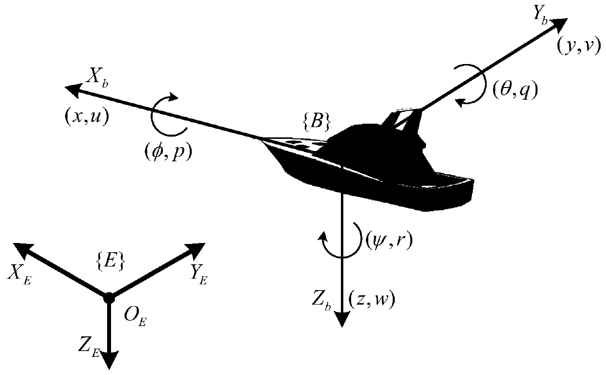
[0068] η=[x,y,ψ] T is the position and heading angle of the USV in the geodetic coordinate system {E}; v=[u,v,r] T is the longitudinal velocity, transverse velocity and heading angular velocity of the USV in the hull coordinate system {B}; J(ψ)∈R 3×3 is the rotation matrix of the UAV from the hull coordinate system {B} to the earth coordinate system {E}; M∈R 3×3 is the inertia matrix; C(v)∈R 3×3 is the matrix of Coriolis force and centripetal force; D∈R 3×3 is the damping force matrix; B∈R 3×2 Configure the matrix for the actuator; f = [f u ,f r ] T is the input quantity of the control, where f u is the propeller thrust, f r is the moment generated by the ...

Embodiment

[0137] In order to verify the effectiveness and efficiency of the path tracking control algorithm proposed by the present invention, it is now applied to an unmanned ship model for verification. In the Cartesian coordinate system, define the X axis as the true east direction, the Y axis as the true north direction, and rotate along the positive half axis of the Y axis.

[0138] The initial state of the unmanned boat is set to [x(0), y(0), ψ(0)] T =[31m,25m,-40°] T 、[u(0),v(0),r(0)] T =[0m / s, 0m / s, 0rad / s] T , with a maximum velocity of v max =2.5m / s, parameter R min = 3m, R k = 2m, δ = 2m, δ max = 30°, k 1 = 3,k 2 =k 3 =k 4 =k 5 = 2, k=0.01, the designed path point information is as follows:

[0139] Table 1 Waypoint information

[0140]

[0141] The simulation effect of the present invention is as Figure 4 to Figure 7 shown, where Figure 4 is the path tracing simulation graph, Figure 5 is the path deviation simulation diagram, Image 6 is the speed ...


PUM


Abstract

The invention discloses a self-adaptive path tracking control method of an unmanned surface vehicle based on waypoints, and belongs to the technical field of control. The method mainly aims at solvinga problem that when a turning angle of an unmanned ship is greater than 90 degrees, classic LOS guidance can generate large overshoot so that turning tracking precision is low. The method comprises the steps of calculating a basic sight angle based on a proposed adaptive LOS circle radius, and compensating the basic sight angle according to path deviation and course deviation to obtain a final expected sight angle; and designing a steering strategy based on a virtual point, and adopting three small-angle steering transition large-angle steering to overcome a serious overshoot problem generated when the turning angle is large. Meanwhile, a navigational speed resolver, an intelligent self-adaptive S-surface course controller and an intelligent self-adaptive integral S-surface navigational speed controller are designed so that tracking efficiency and an anti-interference capability of the unmanned ship can be improved, and complexity and uncertainty of an unmanned ship model can be wellcoped with. The method is mainly used for self-adaptive path tracking control of an unmanned surface vehicle.

Description

technical field [0001] The invention belongs to the technical field of control, and in particular relates to a tracking control method for an unmanned water surface vehicle. Background technique [0002] As an important marine intelligent equipment, the surface unmanned vehicle has played an important role in seabed surveying and mapping, inspection of ocean platforms and offshore wind power plants, marine environment monitoring and offshore reconnaissance and defense. In order to complete tasks accurately and efficiently, at the same time consider Due to the underactuation of the USV and the influence of the complex and changeable ocean environment on its maneuverability, in practical applications, the requirements for the tracking ability of the unmanned vehicle along the preset expected path are getting higher and higher. [0003] In the path tracking control strategy of the unmanned vehicle, the compound straight line path tracking based on the preset path point can be s...

Claims


Application Information

Patent Timeline
Patent Type & Authority Applications(China)
IPC IPC(8): G05D1/02
CPCG05D1/0206
Inventor 牛广智孙延超万磊秦洪德陈哲徐钰斐曹禹
Owner HARBIN ENG UNIV
Why Eureka
Try Eureka