Heat dissipation device for liquid fuel cell system

A liquid fuel cell and heat sink technology, which is applied in the directions of fuel cell heat exchange, fuel cell, fuel cell auxiliary, etc. The effect of simplicity, reduced processing difficulty, and compact layout

Pending Publication Date: 2020-08-04
上海醇加能源科技有限公司
View PDF0 Cites 2 Cited by
  • Summary
  • Abstract
  • Description
  • Claims
  • Application Information

AI Technical Summary

Problems solved by technology

However, at present, the expansion method of increasing the heat dissipation area by adding fins is almost extreme, and it is difficult to increase the heat dissipation capacity of the radiator over a larger span. on the issue of difficulty
The pipes and fins of traditional radiators need to be welded, and there are strict requirements for the distance between tubes of different diameters, which limits the size of the radiator and increases the difficulty of processing

Method used


Image

  • Heat dissipation device for liquid fuel cell system
  • Heat dissipation device for liquid fuel cell system
  • Heat dissipation device for liquid fuel cell system

Examples


Embodiment Construction

[0027] The present invention will be further described below in conjunction with the accompanying drawings and embodiments.

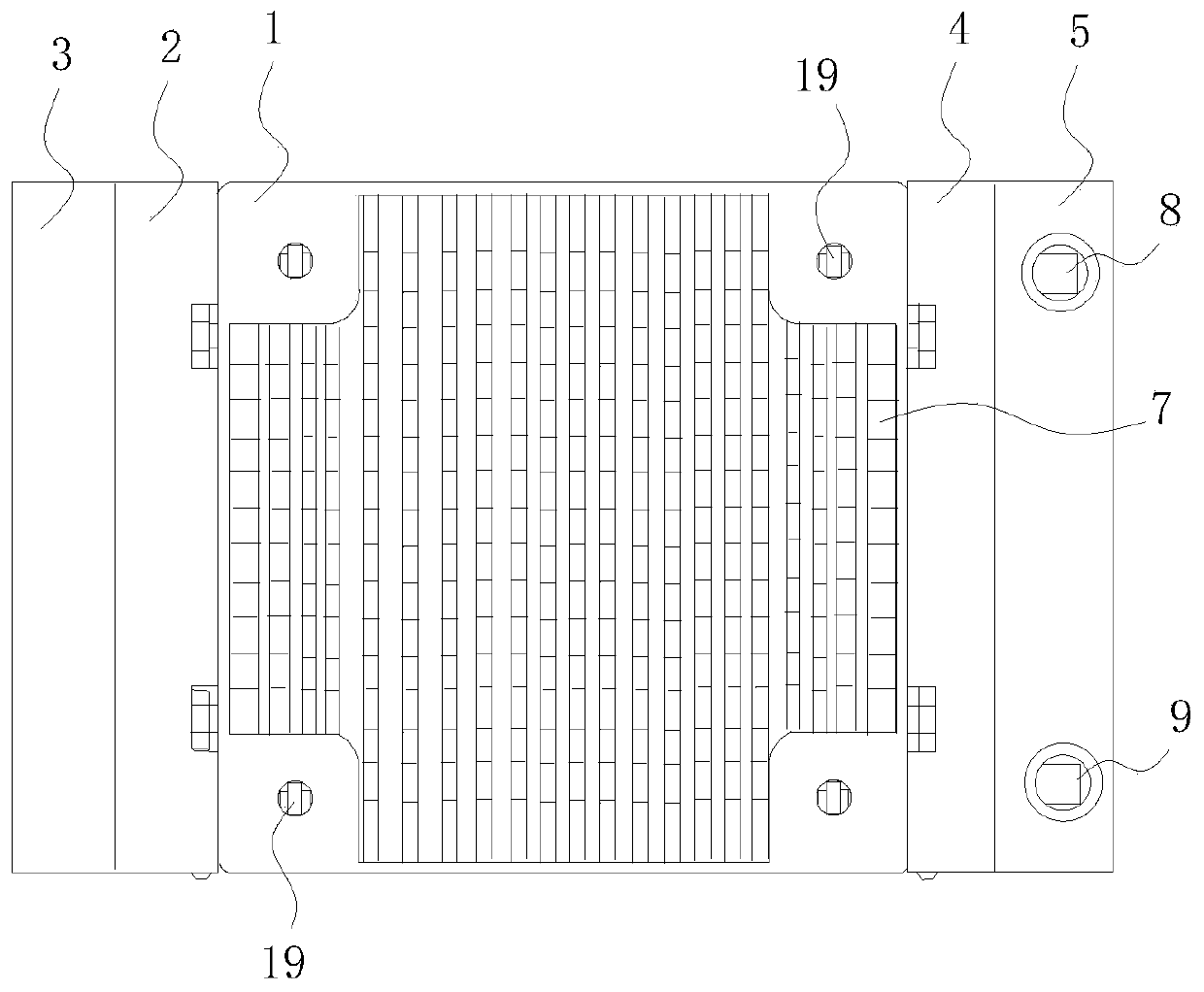
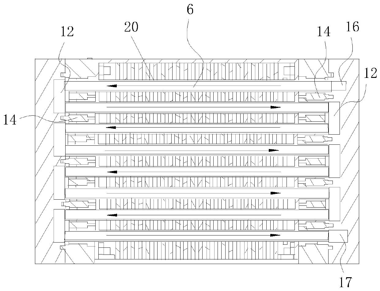
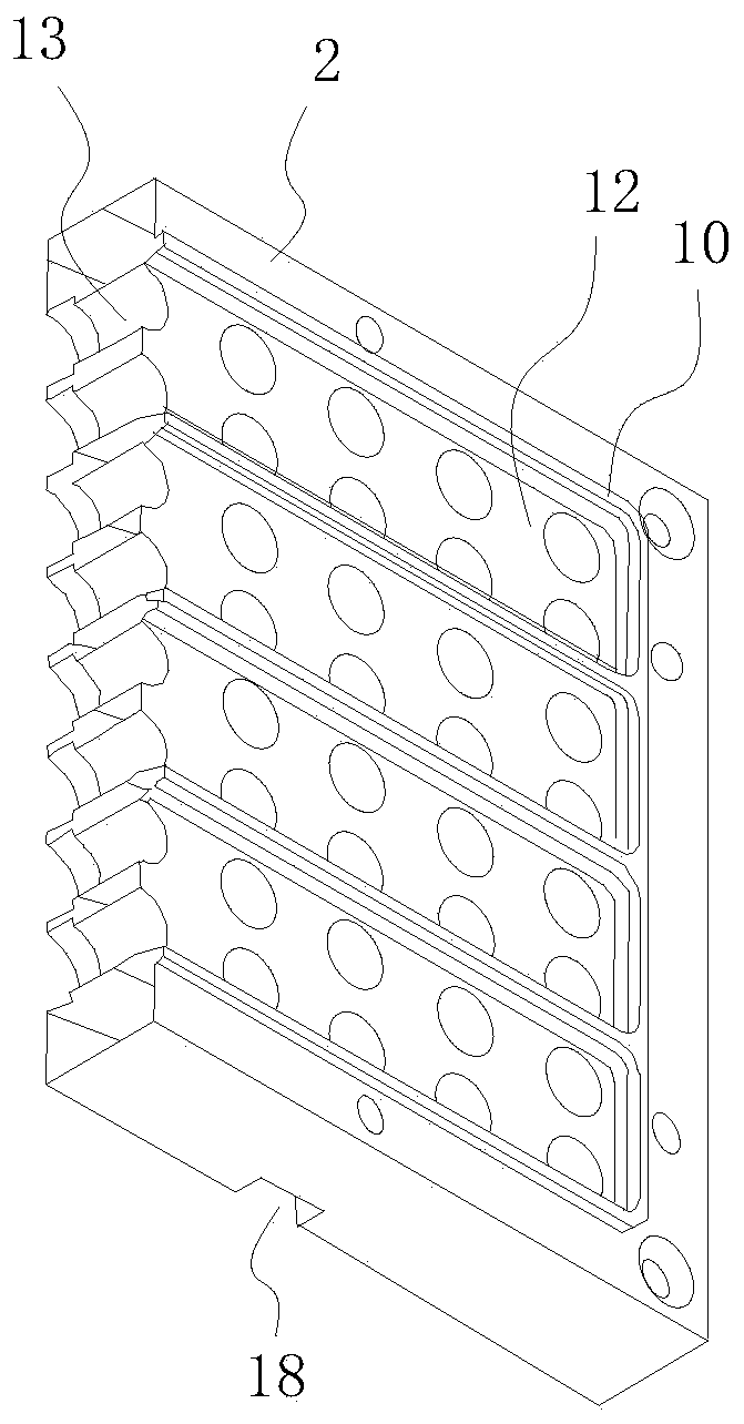
[0028] Such as Figure 1-6 As shown, the cooling device for the liquid fuel cell system of this embodiment includes a fixed frame 1, a left end plate 3 arranged on the left side of the fixed frame 1 through a left fixed plate 2, and a left end plate 3 arranged on the left side of the fixed frame 1 through a right fixed plate 4. The right end plate 5 on the right side of the fixed frame 1, several pipes 6 arranged in the fixed frame 1, several fins 7 arranged in the fixed frame 1, and the feed inlet 8 arranged on the right end plate 5 and the discharge port 9, the pipe 6 passes through the fin 7, the pipe 6 connects the feed port 8 and the discharge port 9, several pipes 6 are arranged in several layers in the fixed frame 1, the left fixed plate 2 and the right The fixed plates 4 are provided with grooved rectangular channels 12 for communicating with t...


PUM

PropertyMeasurementUnit
heightaaaaaaaaaa

Abstract

The invention discloses a heat dissipation device for a liquid fuel cell system. The heat dissipation device comprises a fixed frame, a left side end plate arranged in the left side of the fixed framethrough a left side fixed plate, a right side end plate arranged in the right side of the fixed frame through a right side fixed plate, a plurality of pipelines arranged in the fixed frame, a plurality of fins arranged in the fixed frame, and a feeding hole and a discharging hole formed in the right side end plate; the pipelines penetrate through the fins and enable the feeding port and the discharging port to be communicated, the multiple pipelines are arranged into a plurality of layers in the fixed frame, and the left side fixed plate and the right side fixed plate are each provided with agroove rectangular flow channel communicated with the two adjacent layers of pipelines. According to the heat dissipation device for the liquid fuel cell system, through the design of the groove rectangular flow channels in the fixed plates at the two sides, the process difficulty that the joints of every two adjacent layers of pipeline elbows need to be welded is solved, the structure is simple,and the machining difficulty of the heat dissipation device is reduced.

Description

technical field [0001] The invention relates to the technical field of fuel cells, in particular to a cooling device for a liquid fuel cell system. Background technique [0002] Fuel cell is a chemical device that directly converts the chemical energy of fuel into electrical energy. It is the fourth power generation technology after hydropower, thermal power and atomic power. Fuel cells have high power generation efficiency, low noise and low emissions, and are the most promising green power generation technology. Theoretically, the fuel cell can operate at a thermal efficiency close to 100%, but the actual conversion efficiency is mostly 25%-60%, and about 40%-75% of the internal energy of the fuel becomes waste heat in the reaction process. If it is not discharged in time, it will As a result, the local heat inside the battery continues to rise, endangering the normal operation of the battery. [0003] At present, there are two main heat dissipation methods widely used i...

Claims


Application Information

Patent Timeline
Patent Type & Authority Applications(China)
IPC IPC(8): H01M8/04014H01M8/0258H01M8/0265H01M8/0273H01M8/0276
CPCH01M8/0258H01M8/0265H01M8/0273H01M8/0276H01M8/04014Y02E60/50
Inventor 阮远强胡华冲汪晔魏伟孙公权李山
Owner 上海醇加能源科技有限公司
Why Eureka
Try Eureka