Wireless charger coil and forming process thereof

A technology of wireless charger and forming process, which is applied in the manufacture of inductors, coils, inductors/transformers/magnets, etc., which can solve the problems of unfavorable charging efficiency, large distance between the transmitting end coil and the receiving end coil, etc., to improve charging efficiency , increase the conductivity efficiency, avoid the effect of melting

Pending Publication Date: 2020-08-04
CHANGZHOU GIAN TECH
View PDF0 Cites 0 Cited by
  • Summary
  • Abstract
  • Description
  • Claims
  • Application Information

AI Technical Summary

Problems solved by technology

The coil of the traditional wireless charger is wound on the surface with enameled wire and nylon wire, and the coil of the traditional wireless charger is separated from the upper cover, so the coil is affected by the enameled wire, nylon wire and the separate installation method, resulting in the late transmitter The distance between the coil and the coil at the receiving end is relatively large, which is not conducive to the improvement of charging efficiency

Method used


Image

  • Wireless charger coil and forming process thereof
  • Wireless charger coil and forming process thereof
  • Wireless charger coil and forming process thereof

Examples


Embodiment 1

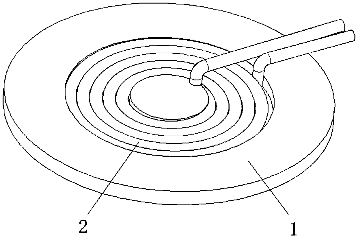
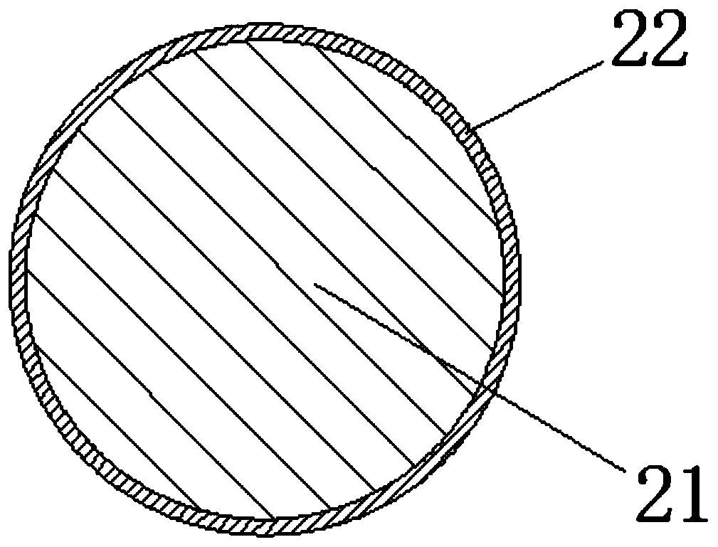
[0035] See Figure 1 to Figure 3 , the wireless charger coil in the present invention includes a coil 2 arranged on the support body 1; the coil 2 is wound by a wire, and the wire is twisted into a strand by a plurality of conductive wires 21; the conductive wire 21 is a copper wire; The surface of each conductive wire 21 is coated with a high temperature resistant insulating glue 22; the model of the high temperature resistant insulating glue 22 is 3M WEICON HT 300.

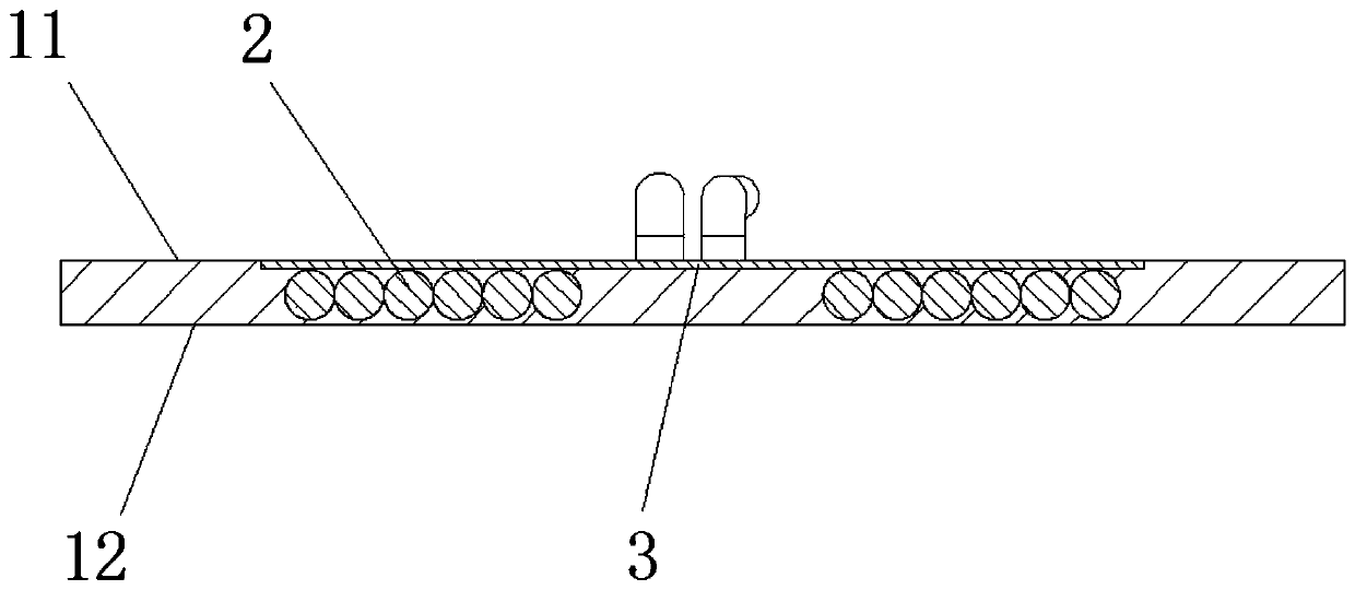
[0036] At the same time, it also has a magnetic sheet 3; the coil 2 and the magnetic sheet 3 are bonded with the support body 1 through integral injection molding after being bonded by high-temperature resistant insulating glue; the coil 2 is embedded on the support body 1; the two ends of the coil 2 The lead wires are exposed outside the base body 1 .

[0037] The equivalent diameter of the wire and the diameter of the conductive wire 21 meet the following conditions:

[0038]

[0039] Wherein, D is the eq...

Embodiment 2

[0048] In the present invention, the magnetic sheet 3 and the coil 2 are not connected in advance during integral injection molding, that is, the coil 2 and the supporting body 1 are formed into an integral part through integral injection molding. Then, the magnetic sheet 3 is connected with the coil 2 as required. At this time, the end surface of the coil 2 located on the installation surface 11 is 0.1-0.2 mm higher than the installation surface 11 . Such setting is to ensure that the magnetic sheet 3 can be attached to the coil 2 when the magnetic sheet 3 is installed later.

[0049] Other technical characteristics are identical with embodiment 1.


PUM

PropertyMeasurementUnit
thermal resistanceaaaaaaaaaa

Abstract

The invention relates to a wireless charger coil and a forming process thereof. The wireless charger coil comprises a coil arranged on a supporting body. The coil is formed by winding a strand of wire, and is characterized in that the wire is formed by twisting a plurality of conductive wires into a strand; the surface of each conductive wire is coated with high-temperature-resistant insulating glue; the coil and the supporting body are integrally formed through integral injection molding, and the coil is embedded in the supporting body; and the leads at the two ends of the coil are exposed out of the supporting body. The forming process comprises the steps of S1 coating a layer of high-temperature-resistant insulating glue on the surfaces of the conductive wires; S2 after the glue is solidified, winding the conductive wires into the coil; and S3 placing the wound coil in an injection mold for injection molding, and an injection molding integrated piece with the coil wrapped by the supporting body is formed. The coil is embedded into the supporting body through integral injection molding, so that the distance between the coil at a transmitting end and the coil at a receiving end inthe later period is shortened, and the charging efficiency is improved.

Description

technical field [0001] The invention relates to the field of wireless charger coil manufacturing, in particular to a wireless charger coil and a forming process thereof. Background technique [0002] At present, the charging principle adopted by the wireless charging industry mainly adopts electromagnetic induction charging. One of the key factors affecting its charging efficiency is: the distance between the transmitting coil and the receiving coil. The smaller the distance, the higher the charging efficiency. The coil of the traditional wireless charger is wound on the surface with enameled wire and nylon wire, and the coil of the traditional wireless charger is separated from the upper cover, so the coil is affected by the enameled wire, nylon wire and the separate installation method, resulting in the late transmitter The distance between the coil and the coil at the receiving end is large, which is not conducive to the improvement of charging efficiency. Contents of t...

Claims


Application Information

Patent Timeline
Patent Type & Authority Applications(China)
IPC IPC(8): H02J50/00H01F38/14H01F41/00H01F41/04H01F41/06H01F41/12
CPCH01F38/14H01F41/005H01F41/04H01F41/06H01F41/12H02J50/005
Inventor 苏绍华李小宝孔佳邬均文王明喜
Owner CHANGZHOU GIAN TECH
Why Eureka
Try Eureka