Soil remediation bioreactor

A bioreactor and soil remediation technology, applied in the field of bioreactors, can solve the problems of long treatment period, acidification of underground layers, pollution of underground rivers, etc., and achieve the effect of convenient backfill treatment and avoid powdering of soil particles

Inactive Publication Date: 2020-08-07
HAINAN UNIVERSITY
View PDF8 Cites 0 Cited by
  • Summary
  • Abstract
  • Description
  • Claims
  • Application Information

AI Technical Summary

Problems solved by technology

[0003] Due to the long treatment period and generally placed on the spot, when the reactor mixes and grinds the polluted soil in an internal mixing cycle, although the excessively fine soil is conducive to the microbial reaction, the colloidal particles inside the soil are easily infiltrated in the fine soil Water affects leaching, which will easily lead to the loss of nutrients to the underground layer after the treatment is completed, resulting in acidification of the underground layer or pollution of underground rivers

Method used


Image

  • Soil remediation bioreactor
  • Soil remediation bioreactor
  • Soil remediation bioreactor

Examples


Embodiment 1

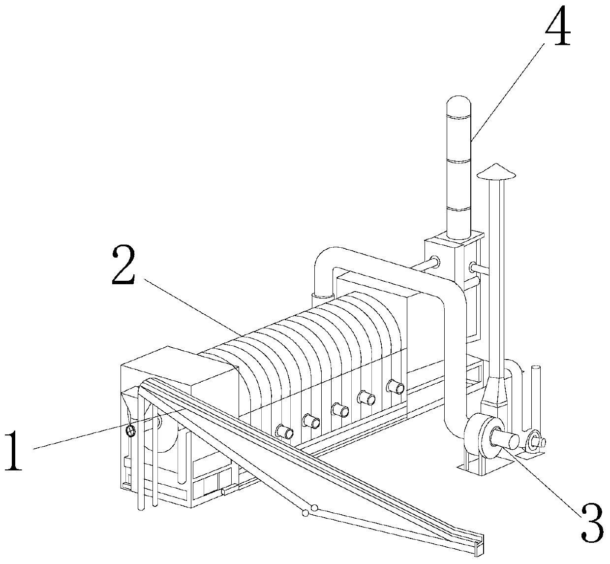
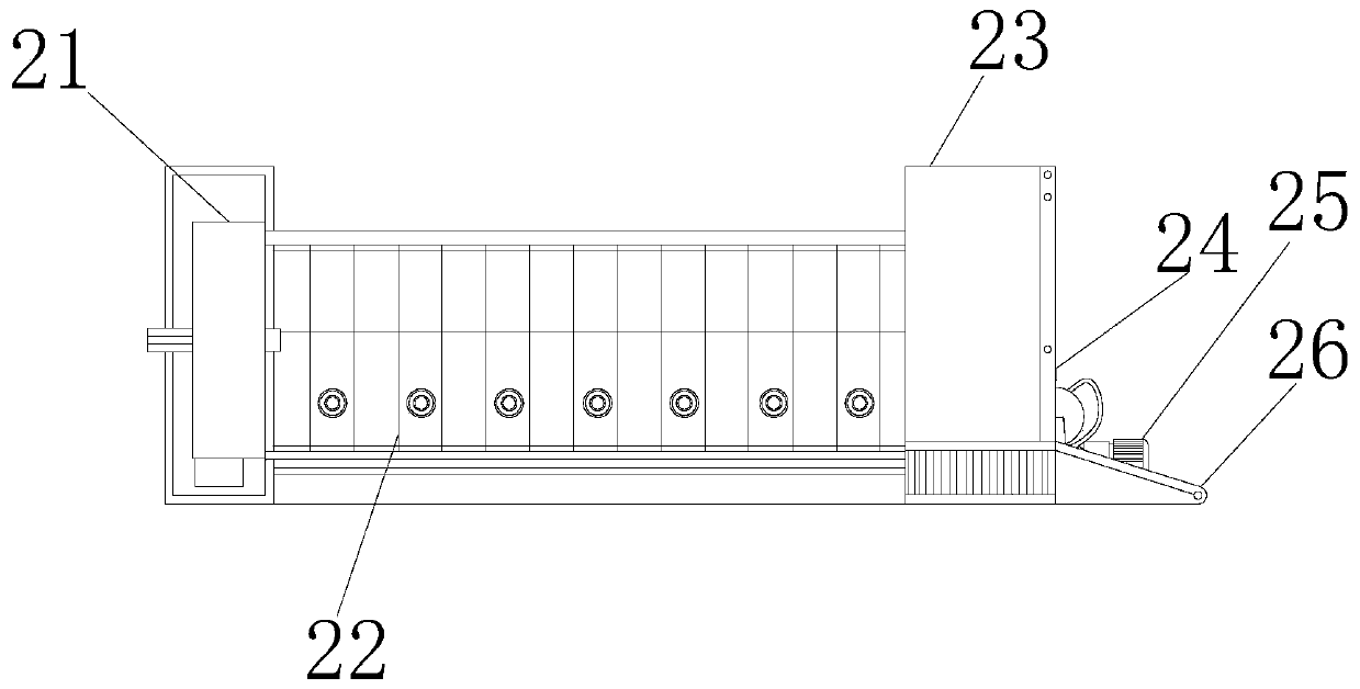
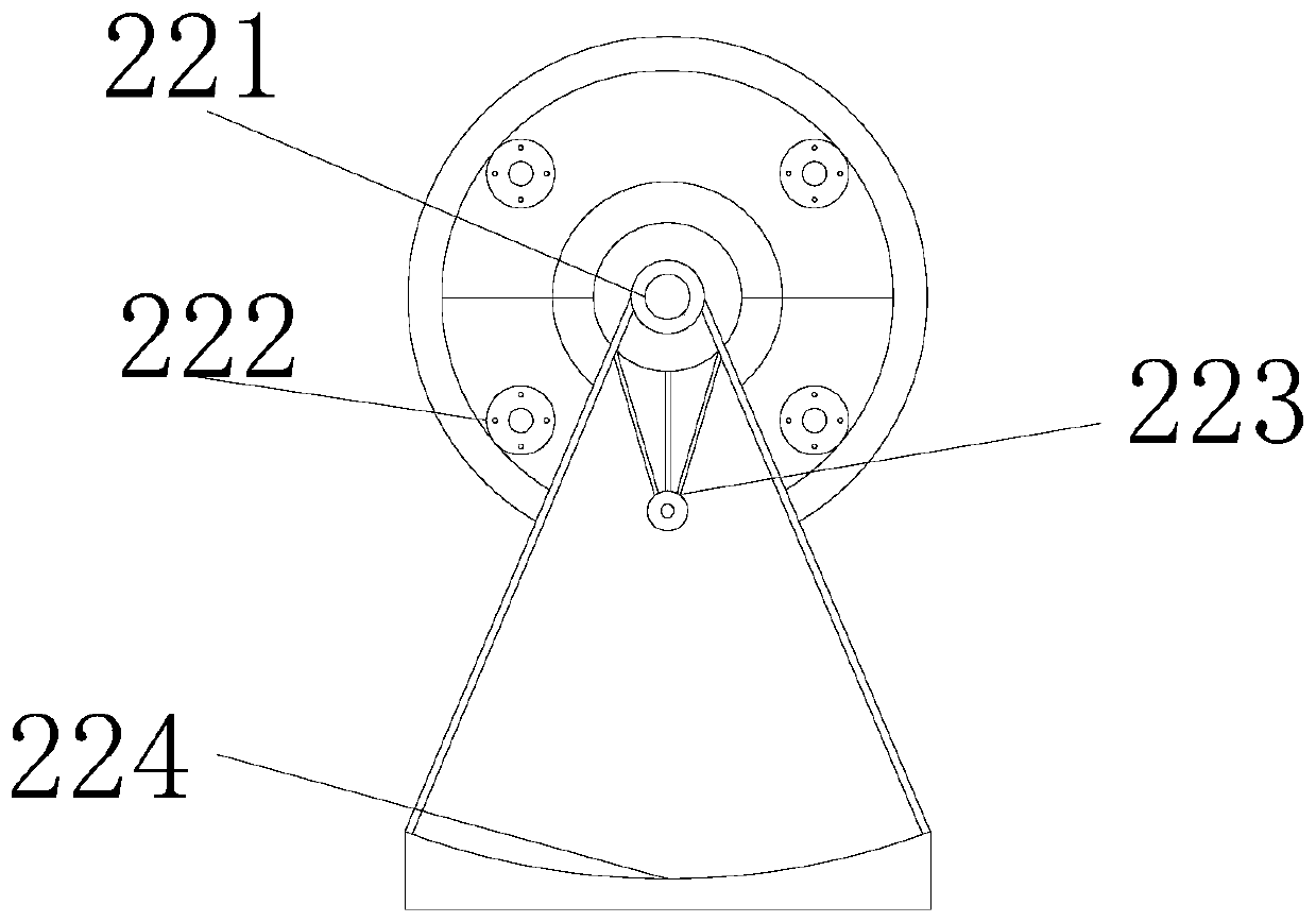
[0025] as attached figure 1 to attach Figure 6 Shown:

[0026] The present invention provides a soil repair bioreactor, the structure of which includes a feed belt 1, a repair box 2, a turbine 3, and a nutrient solution tank 4. The top of the feed belt 1 is attached to the side of the repair box 2, and the repair The side of the box 2 is connected to the side pipe of the turbine 3, the middle section of the nutrient solution tank 4 is connected to the top pipeline of the repair box 2, the middle section of the nutrient solution tank 4 is connected to the top pipe of the turbine 3, and the repair box 2 is provided with a preliminary screening plate 21 , mud mixing cylinder 22, reaction tank 23, winch 24, water pump 25, discharge belt 26, the side of the first screening plate 21 is connected to the side flange of the mud mixing cylinder 22, and the other side of the mud mixing cylinder 22 is connected to the reaction tank. The side flange of the tank 23 is connected, the bott...

Embodiment 2

[0034] as attached Figure 7 Shown:

[0035] Wherein, the grinding tube 22b is provided with an inner pad h1, an inner container h2, a mesh h3, and a connection port h4, the outer surface of the inner pad h1 is movable with the inner surface of the inner container h2, and the outer surface of the inner container h2 is in contact with the grinding surface. The inner wall of the pipe 22b is nested and connected, the center of the screen hole h3 is connected with the surface wall of the inner tank h2, the side wall of the connecting port h4 is perforated and matched with the bottom of the inner tank h2, and the side wall of the connecting port h4 is embedded with the side of the connecting rod 22d. Sleeve connection, the sieve holes h3 are distributed symmetrically from left to right, and the surface of the inner pad h1 is in a ring-shaped distribution structure with dense grooves, which can better maintain the particle size during the grinding process and avoid grinding too fine...


PUM


Abstract

The invention discloses a soil remediation bioreactor. The soil remediation bioreactor structurally comprises a feeding belt, a repairing box, a turbine and a nutrient solution tank, and the top of the feeding belt is attached to the side face of the repairing box. When soil remediation work is started, the feeding belt runs, to-be-remediated soil is put into a primary screening disc and is pre-screened, large-particle impurities such as stones are screened out to avoid damages to a mud mixing cylinder, the screened soil enters the mud mixing cylinder to wait for mud mixing work, edge out-filling treatment is carried out, during drum mixing, a grinding pipe rotates along the rotating direction of the drum due to inertia, internal mud is ground to facilitate uniform mixing of the soil and amixed liquid, fine mud is filtered out through screen holes, secondary mixing is conducted on the mud on the surface through vibration generated by an inner pad during external operation, grinding pipes are connected in pairs through connecting ports by means of connecting rods to keep the same rotating speed of an inner container during operation, so soil particle pulverization caused by excessive grinding is avoided.

Description

technical field [0001] The invention belongs to the field of bioreactors, in particular to a soil repair bioreactor. Background technique [0002] The soil remediation bioreactor is an instrument that mixes the contaminated soil and water into the reactor, usually placed on the spot, and uses microorganisms to absorb, degrade, and transform the pollutants in the reactor. The period is long. In the actual treatment process, it is necessary to mix and react the bacteria and soil fully by stirring and spraying to ensure that the treatment bacteria multiply to form a biofilm, and to further reduce the concentration of pollutants through cyclic treatment. Based on the above inventors' discovery, The existing ones mainly have the following deficiencies, such as: [0003] Due to the long treatment period and generally placed on the spot, when the reactor is internally mixed with drums, grinds and circulates to filter the contaminated soil, although the excessively fine soil is con...

Claims


Application Information

Patent Timeline
Patent Type & Authority Applications(China)
IPC IPC(8): B09C1/10B02C17/02B02C17/10B02C17/20B02C23/14C12M1/12C12M1/02C12M1/00
CPCB02C17/02B02C17/10B02C17/20B02C23/14B09C1/10C12M23/02C12M27/02C12M33/14
Inventor 陈明春
Owner HAINAN UNIVERSITY
Why Eureka
Try Eureka