
Multifunctional grinding head mechanism and main shaft

A multi-functional grinding head and grinding head technology, applied in the field of polishing machines, can solve the problems of shortening the service life of the chuck, difficult to replace the brush, difficult to operate, etc. Effect

Pending Publication Date: 2020-08-07
宇晶机器(长沙)有限公司
View PDF0 Cites 2 Cited by
  • Summary
  • Abstract
  • Description
  • Claims
  • Application Information

AI Technical Summary

Problems solved by technology

[0003] At present, the main shaft and quick-change chuck device used in traditional polishing equipment are connected by the main shaft and the chuck handle, the chuck is fixed on the handle, and the brush is fixed by the jacket. This structure is used during use. Due to the splash of polishing liquid into the jacket, it will cause the accumulation of abrasive powder, making it difficult to replace the brush, and shorten the service life of the chuck, which is not only difficult to operate but also increases the cost

Method used


Image

  • Multifunctional grinding head mechanism and main shaft
  • Multifunctional grinding head mechanism and main shaft
  • Multifunctional grinding head mechanism and main shaft

Examples


Embodiment 1

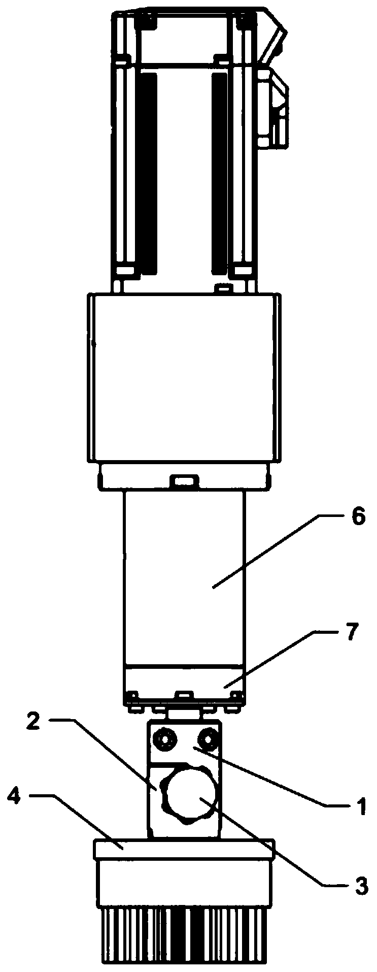
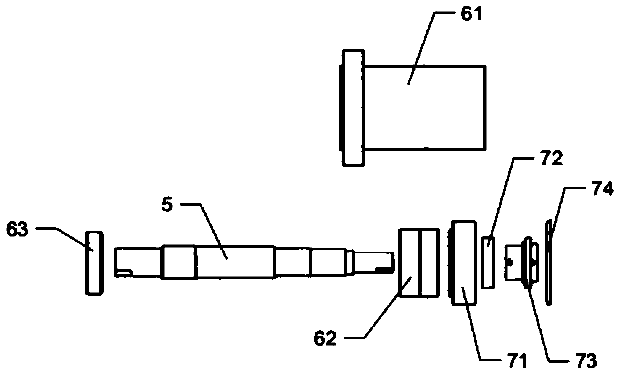
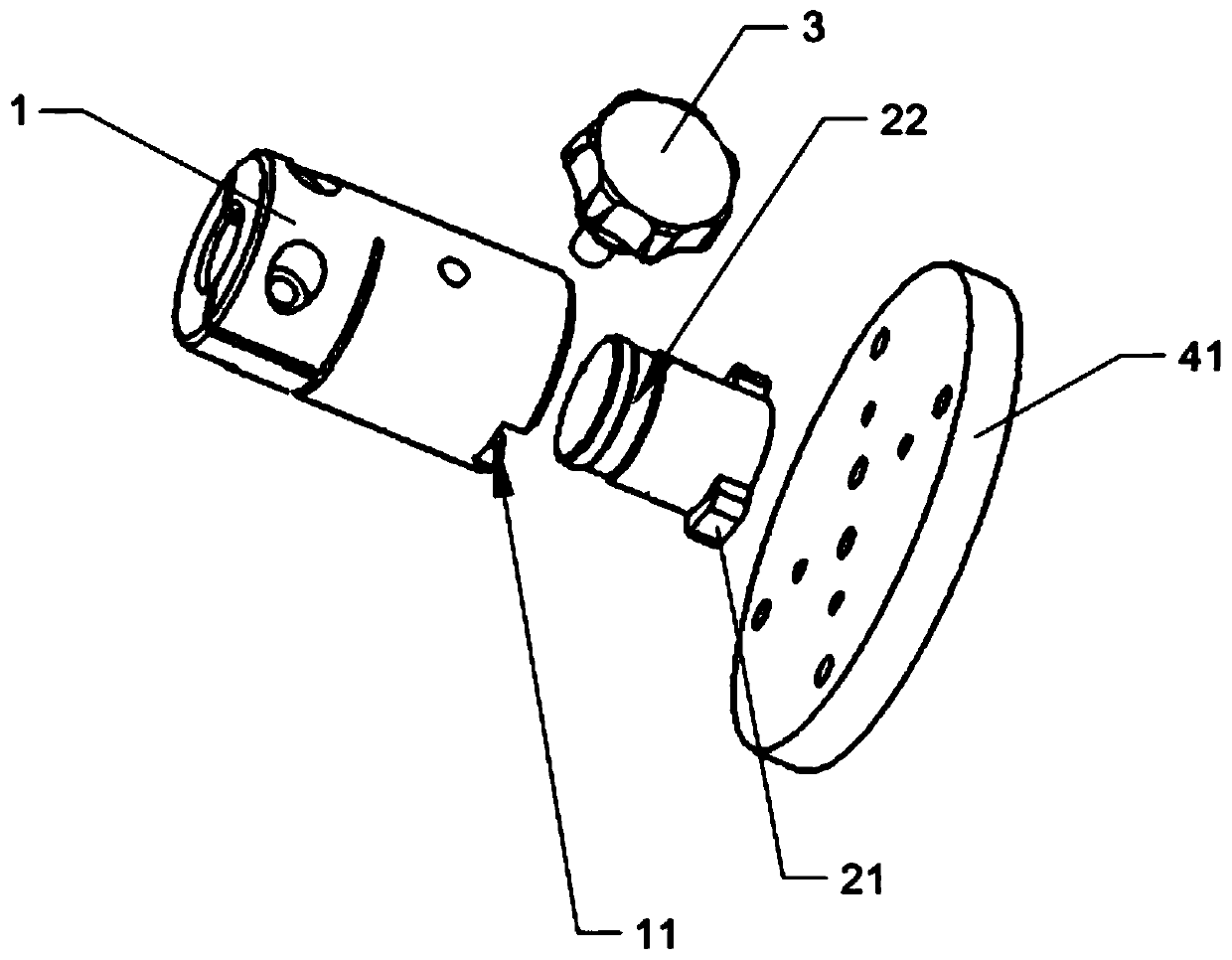
[0025] Refer to attached Figure 1-4 , this embodiment includes: a chuck handle 1, a grinding head handle 2 and a handle 3, the grinding head handle 2 is inserted into the chuck connecting handle 1, the outer wall of the grinding head handle 2 is provided with lugs 21, and the chuck handle 1 is provided with The first limiting groove 11 matching the lug 21, the outer peripheral wall of the grinding head handle 2 is provided with a second limiting groove 22 matching the handle 3, the handle 3 is threadedly connected with the chuck handle 1, and One end is inserted into the second limiting groove 22 to lock the grinder handle 2 . The end of the grinding head handle 2 away from the chuck handle 1 is provided with a first grinding assembly or a second grinding assembly 4 , and the grinding head handle 2 is detachably connected to the first grinding assembly or the second grinding assembly 4 .

[0026] The second grinding assembly 4 includes a brush plate 41, and the brush plate 4...

Embodiment 2

[0034] This embodiment is basically the same as Embodiment 1, the difference is:

[0035] Refer to attached Figure 4-5 , the first grinding assembly includes a grinding head and a fixing bolt, the grinding head handle 2 has a first mounting hole 23 suitable for the grinding head, the fixing bolt is threaded with the grinding head handle 2, and one end is inserted into the first mounting hole 23 and The grinding head abuts to fix the grinding head in the first mounting hole 23 . The grinding head is inserted into the first installation hole 23, and the fixing bolt locks the grinding head. In this embodiment, the fixing bolt is an inner hexagon screw, and when the inner hexagon screw is installed on the grinding head handle 2, it can avoid affecting the insertion of the grinding head handle 2 into the collet adapter 1.

[0036] In the present invention, by setting the lugs 21 and the handle 3, the grinding head handle 2 can be quickly installed on or disassembled from the chu...


PUM


Abstract

The invention discloses a multifunctional grinding head mechanism and a main shaft. The multifunctional grinding head mechanism comprises a chuck receiving handle, a grinding head handle and a handgrip, wherein the grinding head handle is arranged on the chuck receiving handle in an insertion manner, a rotary shaft is arranged on the chuck receiving handle; a sealing mechanism and a transmission mechanism are arranged on the rotary shaft in a sleeved manner; and a lug is arranged on the outer wall of the grinding head handle, a first limit groove adaptive to the lug is formed in the chuck receiving handle, a second limit groove adaptive to the handgrip is formed in the outer circumferential wall of the grinding head handle, the handgrip is in threaded connection with the chuck receiving handle, and a first grinding assembly or a second grinding assembly is arranged at one end away from the chuck receiving handle, of the grinding head handle. Compared with the prior, according to the multifunctional grinding head mechanism and the main shaft, through the arrangement for the lug and the handle, the grinding head handle can be rapidly fixed to the chuck receiving handle, and the structure is capable of avoiding the accumulation of grinding powder, so that the service life of the structure is prolonged; and due to separate design for the grinding head handle, the first grinding assembly and the second grinding assembly, cost reduction is benefited. The grinding head or a brush disc can be rapidly replaced as needed by rotating the handgrip, so that the working efficiency can beeffectively increased.

Description

technical field [0001] The invention relates to the technical field of polishing machines, in particular to a multifunctional grinding head mechanism and a main shaft. Background technique [0002] As a kind of polishing equipment, the single-side polishing machine is widely used in the special-shaped surface polishing of 2.5D, 3D glass, sapphire and other hard and brittle materials. The spindle device is one of the core components of the single-side polishing machine. The polishing precision requirements of similar glass, and the quick-change chuck shaft is the key part connecting the rotating shaft and the polishing head. So the reasonable design of its structure is very important. [0003] At present, the main shaft and quick-change chuck device used in traditional polishing equipment are connected by the main shaft and the chuck handle, the chuck is fixed on the handle, and the brush is fixed by the jacket. This structure is used during use. The polishing liquid splash...

Claims


Application Information

Patent Timeline
Patent Type & Authority Applications(China)
IPC IPC(8): B24B41/04B24B45/00F16H57/04F16H57/021F16H57/029
CPCB24B41/04B24B45/003B24B45/006F16H57/04F16H57/021F16H57/029
Inventor 杨佳葳王珲荣
Owner 宇晶机器(长沙)有限公司
Learn More