
Rail traffic three-layer single-column assembly type overhead station

A rail transit and prefabricated technology, applied in the field of rail transit, can solve problems such as poor permeability of station overhead floors and station hall floors, difficulty in ensuring the quality of cast-in-place concrete construction, and poor effects of station interiors and urban landscapes, etc., to achieve optimization The arrangement of pillars on the station hall floor shortens the construction period and improves the construction quality

Pending Publication Date: 2020-08-07
BEIJING URBAN CONSTR DESIGN & DEV GRP CO
View PDF0 Cites 3 Cited by
  • Summary
  • Abstract
  • Description
  • Claims
  • Application Information

AI Technical Summary

Problems solved by technology

[0003] Dry-type stations with traditional consolidated system structures often adopt concrete structures and cast-in-place construction methods for brackets. The construction process takes a long time on the road, seriously affecting road traffic, and the construction quality of cast-in-place concrete is difficult to guarantee
[0004] In the traditional single-column dry-shaped station, the pier column on the first floor directly leads to the lower layer of the platform slab, and a large cross-section pier column is set in the middle of the station hall layer, which is not conducive to the building layout, affects the use function, affects the visual effect, and affects the comfort of passengers poor
[0005] The traditional single-column dry-shaped station has a concrete frame beam member in the longitudinal direction, and the longitudinal span of the station is limited by the spanning capacity of the concrete. The span is usually 12-13m, so the permeability of the overhead floor and the station hall floor of the station is poor. The interior of the station and the urban landscape are poor

Method used


Image

  • Rail traffic three-layer single-column assembly type overhead station
  • Rail traffic three-layer single-column assembly type overhead station
  • Rail traffic three-layer single-column assembly type overhead station

Examples


Embodiment Construction

[0030] In order to make the purpose, technical solution and advantages of the present invention clearer, the present invention will be further described in detail below with reference to the accompanying drawings and embodiments. It should be understood that the specific embodiments described here are only used to explain the present invention, but not to limit the present invention.

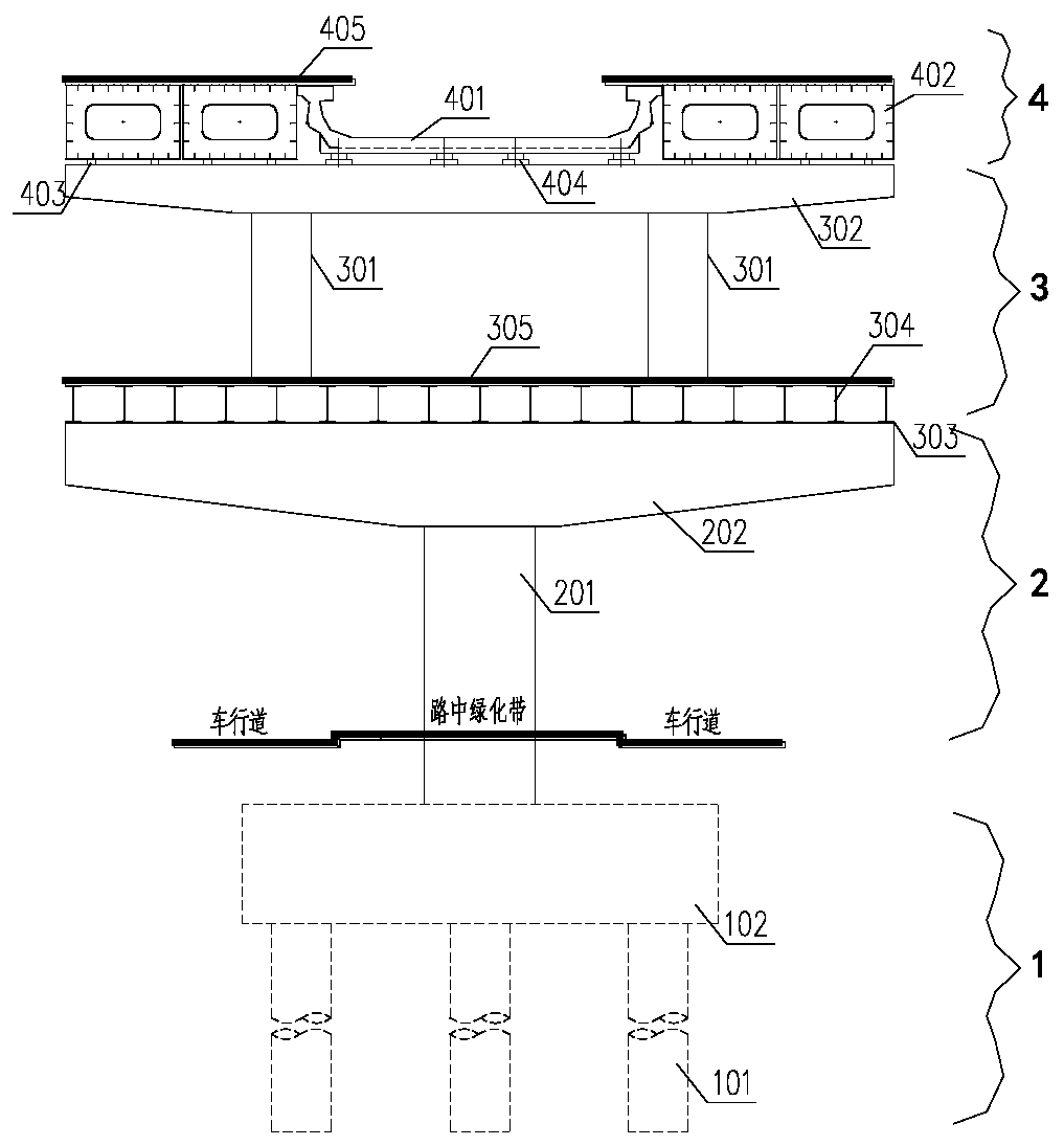
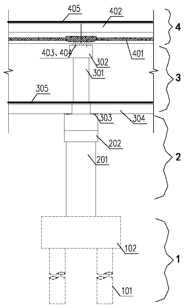
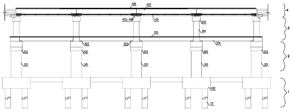
[0031] see figure 1 , figure 2 with image 3 , shows the rail transit three-layer single-column assembled elevated station of the present invention.

[0032] The rail transit three-story single-column assembled elevated station includes a station foundation 1 and a three-story structure above the station foundation 1, and the three-story structure includes an overhead floor 2 on the first floor, a station hall floor 3 on the second floor, and a three-story building. Platform layer 4, wherein, the station foundation 1 can adopt a pile foundation or an enlarged foundation according to geologic...


PUM


Abstract

The invention relates to a rail traffic three-layer single-column assembly type overhead station. The rail traffic three-layer single-column assembly type overhead station comprises a three-layer structure, wherein the first layer is an overhead layer, the second layer is a station hall layer, and the three layer is a platform layer. A single column pier of the overhead layer is arranged on a baseand supports a cantilevered beam to form a single-column T-shaped structure. A transverse double column of the station hall layer is erected on the overhead layer cantilevered beam and supports a single span cantilevered cross beam to form a double-column pi-shaped structure. Longitudinal H-shaped steel of the standing hall layer is mounted on a support on the overhead layer cantilevered beam. Aplatform layer rail beam and the platform beam are mounted on a cross beam of the station hall through the support. Therefore, prefabricated assembly construction can be conveniently realized, variouscomponents can be prefabricated and processed in a factory and assembled on the site, assembly type construction of the whole station is completed, the influence on existing road traffic can be reduced, good social and economic benefits are achieved, and good popularization and application values are achieved.

Description

technical field [0001] The present invention relates to the technical field of rail transit, in particular to a rail transit three-layer single-column assembly type that can be used in subway systems, light rail systems, monorail systems, trams, maglev systems, automatic guided rail systems, and urban rapid rail systems. elevated station. Background technique [0002] At present, the lines of domestic rail transit projects are often laid along the middle of the road, and elevated stations are often installed in the green belt in the middle of the road in the form of a single-column structure. Conventional single-column three-story elevated stations often adopt a dry-shaped structure, which is a frame-consolidated system structure . However, the dry-shaped single-column station with the traditional frame consolidation system has the following disadvantages during construction and use: [0003] Dry-shaped stations with traditional consolidated system structures often adopt c...

Claims


Application Information

Patent Timeline
Patent Type & Authority Applications(China)
IPC IPC(8): E04H3/00E02D27/32E02D27/12E02D27/14B61B1/00
CPCB61B1/00E02D27/12E02D27/14E02D27/32E04H3/00
Inventor 白唐瀛杨明虎田志渊刘伟张丁军唐兴国许浩周志亮王汉军于松伟刘运亮张晓康杨铮任静刘颖夏赞鸥张晓林
Owner BEIJING URBAN CONSTR DESIGN & DEV GRP CO
Learn More