
Power source device

A technology of power source and drive structure, applied in the field of power source, can solve the problems of complex structure of power source, bulky size, difficult speed change, etc., and achieve the effect of light weight, small size and reduced maintenance cost

Pending Publication Date: 2020-08-07
广州山益机械贸易有限公司
View PDF0 Cites 0 Cited by
  • Summary
  • Abstract
  • Description
  • Claims
  • Application Information

AI Technical Summary

Problems solved by technology

[0009] The technical problem to be solved by the present invention is to propose a power source device for the problems of complex structure, bulky volume, high energy consumption and difficult speed change in the prior art. The power source device of the present invention is simple in structure, light in weight, Small size, low energy consumption, high speed and light load can realize stepless speed change, meeting the needs of frequent emergency startup and shutdown of vehicles

Method used


Image

  • Power source device
  • Power source device
  • Power source device

Examples


Embodiment Construction

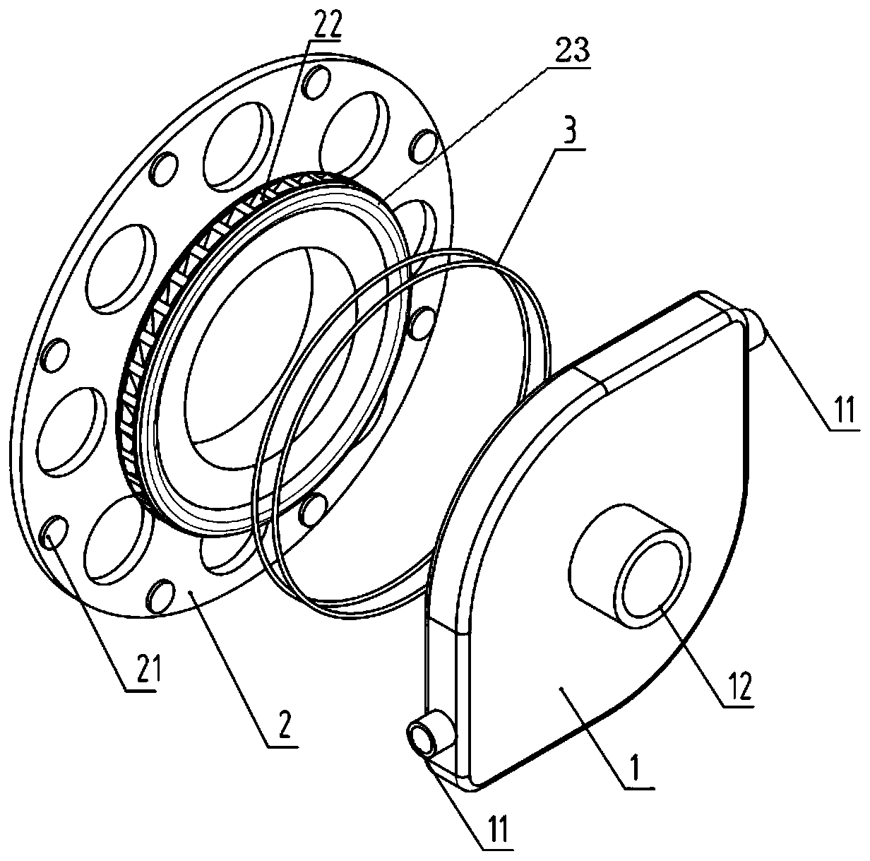
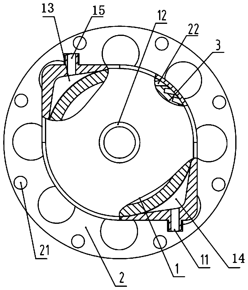
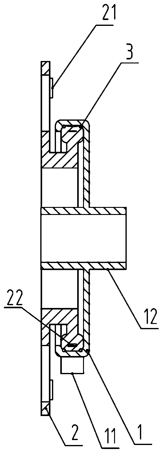
[0028] The following will clearly and completely describe the technical solutions in the embodiments of the present invention with reference to the accompanying drawings in the embodiments of the present invention. Obviously, the described embodiments are only some of the embodiments of the present invention, not all of them. Based on the embodiments of the present invention, all other embodiments obtained by persons of ordinary skill in the art without making creative efforts belong to the protection scope of the present invention.

[0029] Such as Figure 1 to Figure 3 As shown, this embodiment provides a power source device, which includes a housing 1, a driving structure 2, and a sealing assembly 3 arranged between the housing and the driving mechanism. The material used for the sealing assembly is a polymer material or a sealing As for the metal material used, the driving structure 2 is made of an alloy material, preferably an alloy material with high wear resistance, hig...


PUM


Abstract

The invention discloses a power source device. The power source device comprises a shell body, and further comprises a driving mechanism, and a sealing assembly arranged between the shell body and thedriving structure, a cavity body for the flow of a working medium is formed in the shell body, two accommodating cavities for accommodating the working medium are formed in the cavity body, working medium interfaces are correspondingly formed in the two accommodating cavities, and when the working medium flows, the driving mechanism can rotate under the driving of the pressure formed between thetwo accommodating cavities. The power source device has the advantages of simple structure, less weight, small volume, low energy consumption, high speed and light load.

Description

technical field [0001] The invention relates to the technical field of power sources, in particular to a power source device. Background technique [0002] At present, generators are commonly used as power sources to drive the movement of electrical appliances or various machinery and vehicles. Generators are mechanical devices that can convert other forms of energy into electrical energy. They are driven by water turbines, steam turbines, diesel engines or other power machinery. The energy generated by water flow, air flow, fuel combustion or nuclear fission is converted into mechanical energy and transmitted to the generator, which is then converted into electrical energy by the generator. The generators commonly used in vehicles are mainly diesel generators, gasoline generators and hub motors. [0003] The diesel generator converts the energy of diesel into electric energy through the diesel engine. In the cylinder of the diesel engine, the clean air filtered by the air ...

Claims


Application Information

Patent Timeline
Patent Type & Authority Applications(China)
IPC IPC(8): F01D1/34F01D17/10F01D17/14F01D19/00F01D25/24F03B5/00F03B11/02F03B15/00F03B15/02
CPCF01D1/34F01D25/24F01D17/105F01D17/145F01D19/00F03B5/00F03B11/02F03B15/02F03B15/00Y02E10/20
Inventor 赵先知钟亮罗江
Owner 广州山益机械贸易有限公司
Learn More